
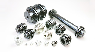
COUPLINGS
Liên hệ
Chúng tôi là nhà phân phối chính thức và duy nhất các sản phẩm của Miki Pulley tại thị trường Việt Nam, Quý khách có nhu cầu về các sản phẩm của Miki Pulley vui lòng liên hệ trực tiếp với chúng tôi để được tư vấn nhanh hơn.
Hotline: 0974190088/Zalo
Email: vuonguoc@gmail.com
COUPLINGS
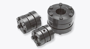
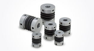
SERVOFLEX
These metal disc-spring couplings with ultra-high torsional stiffness were developed for servo motor applications. The disc-spring method provides excellent properties: firmness in the torsional direction but flexibility in the bending, step-difference, and axial directions. The disc spring that serves as the element has an unbeatable theoretically derived shape that is the result of rigorous analysis with the latest finite element method.
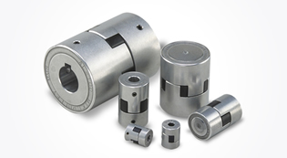
STEPFLEX
STEPFLEX couplings for servo stepping motors that boast high damping performance. Our newly developed laminated rubber element (HNBR) achieves high damping and low reaction force. These couplings absorb vibration faster than flexible couplings that use metal in their elastic components. This suppresses the resonance phenomenon that can occur with stepping motors.
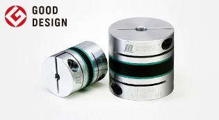
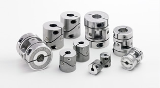
SPRFLEX
These couplings have a simpler design that sandwiches a rubber buffer (nitrile rubber) between two hubs. The hub is lightweight, being made of aluminum alloy. Mounting on a shaft is easy. Simply hold a straight-edge to the hub periphery to center it. One source of appeal is that its simple construction means lower cost.
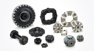
MIKI PULLEY STARFLEX
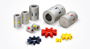
The simple construction of these couplings sandwiches a buffer piece called an element (made of polyurethane elastomer) between two hubs. Elements of two different hardnesses are available so you can select the appropriate one for your torque transmission responsiveness and amount of misalignment. Since the design pre-compresses the element, it can also be used without backlash.
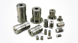
SERVORIGID
These are rigid couplings with ultra-high torsional stiffness that were developed for servo motor applications. Unlike flexible couplings, they have no element to absorb differences between the centers of the two shafts, so they have very high torsional stiffness.
BAUMANNFLEX
These couplings connect a hub that mounts on the shaft to another hub, separated by a metal coil. They achieve excellent flexibility, compact size, and high torque. Different models may connect either a shaft to another shaft or a shaft to a flange.
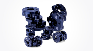
PARAFLEX
These are pin-bushing type couplings whose bodies are made of aluminum alloy. Backlash is kept extremely low by making the torsional stiffness of all components very high and combining high-precision pins with dry metal. A universal system is used for all hub coupling, which makes shaft reaction force due to mounting misalignment extremely small. There is also a damping effect from sliding at the friction surface between the pin and dry metal.
SCHMIDT
When transmitting power between shafts with different centers, which have traditionally been constituted of a spline shaft and a universal joint, Schmidt couplings can be used to efficiently transmit power in a compact form factor. Schmidt couplings are couplings with different shaft centers that use the crank motion of a link. They not only allow power transmission when shaft centers are different, they also enable translation of shaft centers while rotating.
BELLOWFLEX
These couplings absorb vibration and have extremely low counter force caused by mounting misalignment, thanks to the use of a plastic boot made of resin with excellent elastic properties (polyester resins). They are compact and lightweight, since the aluminum alloy hub and boot are designed with a unitized construction. Thanks to the unitized construction, they are easy to mount and remove, and there is no backlash. They come in three sizes, and all are highly flexible couplings that allow eccentricity of 0.5 mm and an angle of deflection of 10°.
CENTAFLEX
Rubber couplings dampen and absorb shock and vibrations using the elasticity of rubber, while plastic couplings do the same with plastics. Their advantages include high flexibility, low noise, easy maintenance (because they do not require lubrication), simple construction, and long service life.
PROSPINE
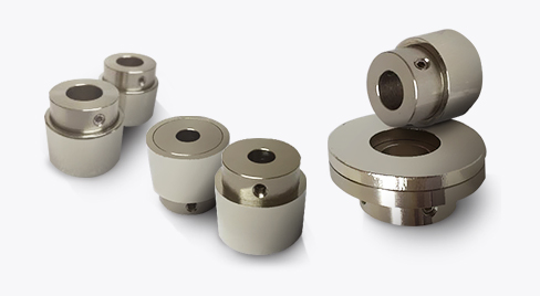
It is a non-contact type coupling that utilizes attraction and repulsion of the magnet and has no contact portion for power transmission, so there is no wear and dust generation of the parts, no noise, vibration and so on.The tolerance of eccentricity and declination in mounting is large, and attachment/detachment can be done very easily.Similar to the general coupling, it can be used as butting axis, as well as other types like parallel axis and orthogonal axis and etc.In addition, since power is transmitted by magnetic force, it can be used as bulkhead transmission and torque limiter function in case of overload.
| Model | Type | Rated torque [N・m] |
Misalignment | Max. rotation speed [min-1] |
Torsional stiffness [N・m/rad] |
Axial stiffness [N/mm] |
Moment of inertia [kg・m2] |
Mass[kg] | ||
|---|---|---|---|---|---|---|---|---|---|---|
| Parallel[mm] | Angular[゜] | Axial[mm] | ||||||||
| SFC-002SA2 | C | 0.25 | 0.01 | 0.5 | ±0.04 | 10000 | 190 | 34 | 0.06×10⁻⁶ | 0.003 |
| SFC-005SA2 | C | 0.6 | 0.02 | 0.5 | ±0.05 | 10000 | 500 | 140 | 0.26×10⁻⁶ | 0.007 |
| SFC-010SA2 | C | 1 | 0.02 | 1 | ±0.1 | 10000 | 1400 | 140 | 0.58×10⁻⁶ | 0.011 |
| SFC-020SA2 | C | 2 | 0.02 | 1 | ±0.15 | 10000 | 3700 | 64 | 2.39×10⁻⁶ | 0.025 |
| SFC-025SA2 | C | 4 | 0.02 | 1 | ±0.19 | 10000 | 5600 | 60 | 3.67×10⁻⁶ | 0.029 |
| SFC-030SA2 | A | 5 | 0.02 | 1 | ±0.2 | 10000 | 8000 | 64 | 4.07×10⁻⁶ | 0.034 |
| B | 6.09×10⁻⁶ | 0.041 | ||||||||
| C | 8.20×10⁻⁶ | 0.049 | ||||||||
| SFC-035SA2 | C | 10 | 0.02 | 1 | ±0.25 | 10000 | 18000 | 112 | 18.44×10⁻⁶ | 0.082 |
| SFC-040SA2 | A | 12 | 0.02 | 1 | ±0.3 | 10000 | 20000 | 80 | 16.71×10⁻⁶ | 0.077 |
| B | 22.55×10⁻⁶ | 0.085 | ||||||||
| C | 29.25×10⁻⁶ | 0.100 | ||||||||
| SFC-050SA2 | A | 25 | 0.02 | 1 | ±0.4 | 10000 | 32000 | 48 | 55.71×10⁻⁶ | 0.159 |
| B | 76.26×10⁻⁶ | 0.177 | ||||||||
| C | 99.03×10⁻⁶ | 0.206 | ||||||||
| SFC-055SA2 | C | 40 | 0.02 | 1 | ±0.42 | 10000 | 50000 | 43 | 188.0×10⁻⁶ | 0.314 |
| SFC-060SA2 | A | 60 | 0.02 | 1 | ±0.45 | 10000 | 70000 | 76.4 | 145.9×10⁻⁶ | 0.283 |
| B | 205.0×10⁻⁶ | 0.326 | ||||||||
| C | 268.6×10⁻⁶ | 0.385 | ||||||||
| SFC-080SA2 | C | 100 | 0.02 | 1 | ±0.55 | 10000 | 140000 | 128 | 710.6×10⁻⁶ | 0.708 |
| SFC-090SA2 | C | 180 | 0.02 | 1 | ±0.65 | 10000 | 100000 | 108 | 1236×10-6 | 0.946 |
| SFC-100SA2 | C | 250 | 0.02 | 1 | ±0.74 | 10000 | 120000 | 111 | 1891×10-6 | 1.202 |
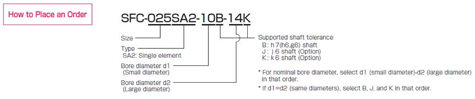
* Types A / B / C are automatically specified by Miki Pulley according to the combination of bore diameters you select, and cannot be specified by the customer.
* Check the Standard Bore Diameter list as rated torque may be restricted by the holding power of the shaft connection component.
* Max. rotation speed does not take into account dynamic balance.
* Torsional stiffness values given are measured values for the element alone.
* The moment of inertia and mass are measured for the maximum bore diameter.
[Dimensions]

| Model | Type | d1[mm] | d2[mm] | D[mm] | DB[mm] | N[mm] | L[mm] | LF[mm] | S[mm] | A1[mm] | A2[mm] | C[mm] | K[mm] | M Qty – Nominal dia |
Tightening torque[N・m] | ||
|---|---|---|---|---|---|---|---|---|---|---|---|---|---|---|---|---|---|
| Min. | Max. | Min. | Max. | ||||||||||||||
| SFC-002SA2 | C | 3 | 5 | 3 | 5 | 12 | 12.4 | ─ | 12.35 | 5.9 | 0.55 | ─ | 3.7 | 1.9 | 5.6 | 1-M1.6 | 0.23~0.28 |
| SFC-005SA2 | C | 3 | 6 | 3 | 6 | 16 | ─ | ─ | 16.7 | 7.85 | 1 | ─ | 4.8 | 2.5 | 6.5 | 1-M2 | 0.4~0.5 |
| SFC-010SA2 | C | 3 | 8 | 3 | 8 | 19 | ─ | ─ | 19.35 | 9.15 | 1.05 | ─ | 5.8(6) | 3.15 | 8.5 | 1-M2.5(M2) | 1.0~1.1(0.4~0.5) |
| SFC-020SA2 | C | 4 | 10 | 4 | 11 | 26 | ─ | ─ | 23.15 | 10.75 | 1.65 | ─ | 9.5 | 3.3 | 10.6 | 1-M2.5 | 1.0~1.1 |
| SFC-025SA2 | C | 5 | 14 | 5 | 14 | 29 | ─ | ─ | 23.4 | 10.75 | 1.9 | ─ | 11 | 3.3 | 14.5 | 1-M2.5 | 1.0~1.1 |
| SFC-030SA2 | A | 5 | 10 | 5 | 10 | 34 | ─ | 21.6 | 27.3 | 12.4 | 2.5 | 8 | ─ | 3.75 | 14.5 | 1-M3 | 1.5~1.9 |
| B | 5 | 10 | Over 10 | 16 | 8 | 12.5 | |||||||||||
| C | Over 10 | 14 | Over 10 | 16 | ─ | ─ | 12.5 | ||||||||||
| SFC-035SA2 | C | 6 | 16 | 6 | 19 | 39 | ─ | ─ | 34 | 15.5 | 3 | ─ | 14 | 4.5 | 17 | 1-M4 | 3.4~4.1 |
| SFC-040SA2 | A | 8 | 15 | 8 | 15 | 44 | ─ | 29.6 | 34 | 15.5 | 3 | 11 | ─ | 4.5 | 19.5 | 1-M4 | 3.4~4.1 |
| B | 8 | 15 | Over 15 | 24 | 11 | 17 | |||||||||||
| C | Over 15 | 19 | Over 15 | 24 | ─ | ─ | 17 | ||||||||||
| SFC-050SA2 | A | 8 | 19 | 8 | 19 | 56 | ─ | 38 | 43.4 | 20.5 | 2.4 | 14.5 | ─ | 6 | 26 | 1-M5 | 7.0~8.5 |
| B | 8 | 19 | Over 19 | 30 | 14.5 | 22 | |||||||||||
| C | Over 19 | 25 | Over 19 | 30 | ─ | ─ | 22 | ||||||||||
| SFC-055SA2 | C | 10 | 30 | 10 | 30 | 63 | ─ | ─ | 50.6 | 24 | 2.6 | ─ | 23 | 7.75 | 31 | 1-M6 | 14~15 |
| SFC-060SA2 | A | 11 | 24 | 11 | 24 | 68 | ─ | 46 | 53.6 | 25.2 | 3.2 | 17.5 | ─ | 7.75 | 31 | 1-M6 | 14~15 |
| B | 11 | 24 | Over 24 | 35 | 17.5 | 26.5 | |||||||||||
| C | Over 24 | 30 | Over 24 | 35 | ─ | ─ | 26.5 | ||||||||||
| SFC-080SA2 | C | 18 | 35 | 18 | 40 | 82 | ─ | ─ | 68 | 30 | 8 | ─ | 28 | 9 | 38 | 1-M8 | 27~30 |
| SFC-090SA2 | C | 25 | 40 | 25 | 45 | 94 | ─ | ─ | 68.3 | 30 | 8.3 | ─ | 34 | 9 | 42 | 1-M8 | 27~30 |
| SFC-100SA2 | C | 32 | 45 | 32 | 45 | 104 | ─ | ─ | 69.8 | 30 | 9.8 | ─ | 39 | 9 | 48 | 1-M8 | 27~30 |
* Types A / B / C are automatically specified by Miki Pulley according to the combination of bore diameters you select, and cannot be specified by the customer.
* The øDB value is measured assuming that the head of the clamping bolt is larger than the external diameter of the hub.
* The K dimension is the inner diameter of the element. For d2 dimension exceeding this value, shaft can be inserted only up to LF dimension to the d2 side hub.
* The nominal diameter for the clamping bolt M is equal to the quantity minus the nominal diameter of the screw threads, where the quantity is for a hub on one side.
* The figures in parentheses ( ) for the SFC-010 are the values when d1 or d2 is ø8 mm.
[Standard bore diameter]
| Standard (option) bore diameter, d1/d2 [mm] and restricted rated torque [N∙m] | |||||||||||||||||||||||||||||||||
|---|---|---|---|---|---|---|---|---|---|---|---|---|---|---|---|---|---|---|---|---|---|---|---|---|---|---|---|---|---|---|---|---|---|
| Nominal bore diameter | 3 | 4 | 5 | 6 | 6.35 | 7 | 8 | 9 | 9.525 | 10 | 11 | 12 | 13 | 14 | 15 | 16 | 17 | 18 | 19 | 20 | 22 | 24 | 25 | 28 | 30 | 32 | 35 | 38 | 40 | 42 | 45 | ||
| Shaft tolerance | h7(h6・g6) | B | ● | ● | ● | ● | ● | ● | ● | ● | ● | ● | ● | ● | ● | ● | ● | ● | ● | ● | ● | ● | ● | ● | ● | ● | ● | ● | ● | ● | ● | ● | ● |
| j6(Option) | J | ○ | ○ | ○ | ○ | ||||||||||||||||||||||||||||
| k6(Option) | K | ○ | ○ | ○ | ○ | ○ | ○ | ○ | ○ | ○ | |||||||||||||||||||||||
| Supported bore diameter for each mode |
SFC-002SA2 | d1 | ● | ● | ● | ||||||||||||||||||||||||||||
| d2 | ● | ● | ● | ||||||||||||||||||||||||||||||
| SFC-005SA2 | d1 | ● | ● | ● | ● | ||||||||||||||||||||||||||||
| d2 | ● | ● | ● | ● | |||||||||||||||||||||||||||||
| SFC-010SA2 | d1 | ● | ● | ● | ● | ● | ● | ● | |||||||||||||||||||||||||
| d2 | ● | ● | ● | ● | ● | ● | ● | ||||||||||||||||||||||||||
| SFC-020SA2 | d1 | ● | ● | ● | ● | ● | ● | ● | ● | ● | |||||||||||||||||||||||
| d2 | ● | ● | ● | ● | ● | ● | ● | ● | ● | ● | |||||||||||||||||||||||
| SFC-025SA2 | d1 | 2.1 | ● | ● | ● | ● | ● | ● | ● | ● | ● | ● | ● | ||||||||||||||||||||
| d2 | 2.1 | ● | ● | ● | ● | ● | ● | ● | ● | ● | ● | ● | |||||||||||||||||||||
| SFC-030SA2 | d1 | 2.8 | 3.4 | ● | ● | ● | ● | ● | ● | ● | ● | ● | ● | ||||||||||||||||||||
| d2 | 2.8 | 3.4 | ● | ● | ● | ● | ● | ● | ● | ● | ● | ● | ● | ● | |||||||||||||||||||
| SFC-035SA2 | d1 | 5 | 5 | 6.6 | ● | ● | ● | ● | ● | ● | ● | ● | ● | ● | |||||||||||||||||||
| d2 | 5 | 5 | 6.6 | ● | ● | ● | ● | ● | ● | ● | ● | ● | ● | ● | ● | ● | |||||||||||||||||
| SFC-040SA2 | d1 | 9 | ● | ● | ● | ● | ● | ● | ● | ● | ● | ● | ● | ● | |||||||||||||||||||
| d2 | 9 | ● | ● | ● | ● | ● | ● | ● | ● | ● | ● | ● | ● | ● | ● | ● | |||||||||||||||||
| SFC-050SA2 | d1 | 18 | 20 | 22 | 22 | ● | ● | ● | ● | ● | ● | ● | ● | ● | ● | ● | ● | ● | |||||||||||||||
| d2 | 18 | 20 | 22 | 22 | ● | ● | ● | ● | ● | ● | ● | ● | ● | ● | ● | ● | ● | ● | ● | ||||||||||||||
| SFC-055SA2 | d1 | 31 | 34 | 36 | 38 | ● | ● | ● | ● | ● | ● | ● | ● | ● | ● | ● | ● | ||||||||||||||||
| d2 | 31 | 34 | 36 | 38 | ● | ● | ● | ● | ● | ● | ● | ● | ● | ● | ● | ● | |||||||||||||||||
| SFC-060SA2 | d1 | 50 | 51 | ● | ● | ● | ● | ● | ● | ● | ● | ● | ● | ● | ● | ● | |||||||||||||||||
| d2 | 50 | 51 | ● | ● | ● | ● | ● | ● | ● | ● | ● | ● | ● | ● | ● | ● | ● | ||||||||||||||||
| SFC-080SA2 | d1 | ● | ● | ● | ● | ● | ● | ● | ● | ● | ● | ||||||||||||||||||||||
| d2 | ● | ● | ● | ● | ● | ● | ● | ● | ● | ● | ● | ● | |||||||||||||||||||||
| SFC-090SA2 | d1 | ● | ● | ● | ● | ● | ● | ● | |||||||||||||||||||||||||
| d2 | ● | ● | ● | ● | ● | ● | ● | ● | ● | ||||||||||||||||||||||||
| SFC-100SA2 | d1 | 226 | ● | ● | ● | ● | ● | ||||||||||||||||||||||||||
| d2 | 226 | ● | ● | ● | ● | ● | |||||||||||||||||||||||||||
* The shaft tolerance for standard bore diameter is h7 (h6 or g6): designation B. However, for a bore diameter of ø35, the shaft tolerance is - 0.025 to +0.010.
* Shaft tolerances j6/k6: designations J/K are optional, and are only supported for bore diameters marked with ○ .
* Bore diameters marked with ● or numbers are supported as the standard bore diameters. Consult Miki Pulley regarding special arrangements which may be possible for other bore diameters.
* Bore diameters whose fields contain numbers are restricted in their rated torque by the holding power of the shaft connection component because the bore diameter is small. The numbers indicate the rated torque [N•m].
SFC-DA2 Types
[Specifications]
| Model | Type | Rated torque [N・m] |
Misalignment | Max. rotation speed [min-1] |
Torsional stiffness [N・m/rad] |
Axial stiffness [N/mm] |
Moment of inertia [kg・m2] |
Mass[kg] | ||
|---|---|---|---|---|---|---|---|---|---|---|
| Parallel[mm] | Angular[゜] | Axial[mm] | ||||||||
| SFC-002DA2 | C | 0.25 | 0.03 | 0.5(On one side) | ±0.08 | 10000 | 95 | 17 | 0.07×10⁻⁶ | 0.004 |
| SFC-005DA2 | C | 0.6 | 0.05 | 0.5(On one side) | ±0.1 | 10000 | 250 | 70 | 0.37×10⁻⁶ | 0.010 |
| SFC-010DA2 | C | 1 | 0.11 | 1(On one side) | ±0.2 | 10000 | 700 | 70 | 0.80×10⁻⁶ | 0.015 |
| SFC-020DA2 | C | 2 | 0.15 | 1(On one side) | ±0.33 | 10000 | 1850 | 32 | 3.43×10⁻⁶ | 0.035 |
| SFC-025DA2 | C | 4 | 0.16 | 1(On one side) | ±0.38 | 10000 | 2800 | 30 | 5.26×10⁻⁶ | 0.040 |
| SFC-030DA2 | A | 5 | 0.18 | 1(On one side) | ±0.4 | 10000 | 4000 | 32 | 7.43×10⁻⁶ | 0.054 |
| B | 9.45×10⁻⁶ | 0.060 | ||||||||
| C | 11.56×10⁻⁶ | 0.068 | ||||||||
| SFC-035DA2 | C | 10 | 0.24 | 1(On one side) | ±0.5 | 10000 | 9000 | 56 | 26.93×10⁻⁶ | 0.121 |
| SFC-040DA2 | A | 12 | 0.24 | 1(On one side) | ±0.6 | 10000 | 10000 | 40 | 29.98×10⁻⁶ | 0.124 |
| B | 35.82×10⁻⁶ | 0.131 | ||||||||
| C | 42.52×10⁻⁶ | 0.146 | ||||||||
| SFC-050DA2 | A | 25 | 0.28 | 1(On one side) | ±0.8 | 10000 | 16000 | 24 | 98.34×10⁻⁶ | 0.250 |
| B | 118.9×10⁻⁶ | 0.268 | ||||||||
| C | 141.7×10⁻⁶ | 0.298 | ||||||||
| SFC-055DA2 | C | 40 | 0.31 | 1(On one side) | ±0.84 | 10000 | 25000 | 21.5 | 261.3×10⁻⁶ | 0.459 |
| SFC-060DA2 | A | 60 | 0.34 | 1(On one side) | ±0.9 | 10000 | 35000 | 38.2 | 256.6×10⁻⁶ | 0.447 |
| B | 315.7×10⁻⁶ | 0.489 | ||||||||
| C | 379.3×10⁻⁶ | 0.549 | ||||||||
| SFC-080DA2 | C | 100 | 0.52 | 1(On one side) | ±1.10 | 10000 | 70000 | 64 | 1039×10-6 | 1.037 |
| SFC-090DA2 | C | 180 | 0.52 | 1(On one side) | ±1.30 | 10000 | 50000 | 54 | 1798×10-6 | 1.369 |
| SFC-100DA2 | C | 250 | 0.55 | 1(On one side) | ±1.48 | 10000 | 60000 | 55.5 | 2754×10-6 | 1.739 |
* Types A / B / C are automatically specified by Miki Pulley according to the combination of bore diameters you select, and cannot be specified by the customer.
* Check the “Standard Bore Diameters” as rated torque may be restricted by the holding power of the shaft connection component.
* Max. rotation speed does not take into account dynamic balance.
* Torsional stiffness values given are measured values for the element alone
* The moment of inertia and mass are measured for the maximum bore diameter.
[Dimensions]

| Model | Type | d1[mm] | d2[mm] | D[mm] | DB[mm] | N[mm] | L[mm] | LF[mm] | LP[mm] | S[mm] | A1[mm] | A2[mm] | C[mm] | d3[mm] | K[mm] | M Qty – Nominal dia |
Tightening torque[N・m] | ||
|---|---|---|---|---|---|---|---|---|---|---|---|---|---|---|---|---|---|---|---|
| Min. | Max. | Min. | Max. | ||||||||||||||||
| SFC-002DA2 | C | 3 | 5 | 3 | 5 | 12 | 12.4 | ─ | 15.7 | 5.9 | 2.8 | 0.55 | ─ | 3.7 | 1.9 | 5.2 | 5.6 | 1-M1.6 | 0.23~0.28 |
| SFC-005DA2 | C | 3 | 6 | 3 | 6 | 16 | ─ | ─ | 23.2 | 7.85 | 5.5 | 1 | ─ | 4.8 | 2.5 | 6.5 | 6.5 | 1-M2 | 0.4~0.5 |
| SFC-010DA2 | C | 3 | 8 | 3 | 8 | 19 | ─ | ─ | 25.9 | 9.15 | 5.5 | 1.05 | ─ | 5.8(6) | 3.15 | 8.5 | 8.5 | 1-M2.5(M2) | 1.0~1.1(0.4~0.5) |
| SFC-020DA2 | C | 4 | 10 | 4 | 11 | 26 | ─ | ─ | 32.3 | 10.75 | 7.5 | 1.65 | ─ | 9.5 | 3.3 | 10.6 | 10.6 | 1-M2.5 | 1.0~1.1 |
| SFC-025DA2 | C | 5 | 14 | 5 | 14 | 29 | ─ | ─ | 32.8 | 10.75 | 7.5 | 1.9 | ─ | 11 | 3.3 | 15 | 14.5 | 1-M2.5 | 1.0~1.1 |
| SFC-030DA2 | A | 5 | 10 | 5 | 10 | 34 | ─ | 21.6 | 37.8 | 12.4 | 8 | 2.5 | 8 | ─ | 3.75 | 15 | 14.5 | 1-M3 | 1.5~1.9 |
| B | 5 | 10 | Over 10 | 16 | 8 | 12.5 | |||||||||||||
| C | Over 10 | 14 | Over 10 | 16 | ─ | ─ | 12.5 | ||||||||||||
| SFC-035DA2 | C | 6 | 16 | 6 | 19 | 39 | ─ | ─ | 48 | 15.5 | 11 | 3 | ─ | 14 | 4.5 | 17 | 17 | 1-M4 | 3.4~4.1 |
| SFC-040DA2 | A | 8 | 15 | 8 | 15 | 44 | ─ | 29.6 | 48 | 15.5 | 11 | 3 | 11 | ─ | 4.5 | 20 | 19.5 | 1-M4 | 3.4~4.1 |
| B | 8 | 15 | Over 15 | 24 | 11 | 17 | |||||||||||||
| C | Over 15 | 19 | Over 15 | 24 | ─ | ─ | 17 | ||||||||||||
| SFC-050DA2 | A | 8 | 19 | 8 | 19 | 56 | ─ | 38 | 59.8 | 20.5 | 14 | 2.4 | 14.5 | ─ | 6 | 26 | 26 | 1-M5 | 7.0~8.5 |
| B | 8 | 19 | Over 19 | 30 | 14.5 | 22 | |||||||||||||
| C | Over 19 | 25 | Over 19 | 30 | ─ | ─ | 22 | ||||||||||||
| SFC-055DA2 | C | 10 | 30 | 10 | 30 | 63 | ─ | ─ | 68.7 | 24 | 15.5 | 2.6 | ─ | 23 | 7.75 | 31 | 31 | 1-M6 | 14~15 |
| SFC-060DA2 | A | 11 | 24 | 11 | 24 | 68 | ─ | 46 | 73.3 | 25.2 | 16.5 | 3.2 | 17.5 | ─ | 7.75 | 31 | 31 | 1-M6 | 14~15 |
| B | 11 | 24 | Over 24 | 35 | 17.5 | 26.5 | |||||||||||||
| C | Over 24 | 30 | Over 24 | 35 | ─ | ─ | 26.5 | ||||||||||||
| SFC-080DA2 | C | 18 | 35 | 18 | 40 | 82 | ─ | ─ | 98 | 30 | 22 | 8 | ─ | 28 | 9 | 40 | 38 | 1-M8 | 27~30 |
| SFC-090DA2 | C | 25 | 40 | 25 | 45 | 94 | ─ | ─ | 98.6 | 30 | 22 | 8.3 | ─ | 34 | 9 | 47 | 42 | 1-M8 | 27~30 |
| SFC-100DA2 | C | 32 | 45 | 32 | 45 | 104 | ─ | ─ | 101.6 | 30 | 22 | 9.8 | ─ | 39 | 9 | 50 | 48 | 1-M8 | 27~30 |
* Types A / B / C are automatically specified by Miki Pulley according to the combination of bore diameters you select, and cannot be specified by the customer.
* The øDB value is measured assuming that the head of the clamping bolt is larger than the external diameter of the hub.
* The K dimension is the inner diameter of the element. For d2 dimension exceeding this value, shaft can be inserted only up to LF dimension to the d2 side hub.
* The nominal diameter for the clamping bolt M is equal to the quantity minus the nominal diameter of the screw threads, where the quantity is for a hub on one side.
* The figures in parentheses ( ) for the SFC-010 are the values when d1 or d2 is ø8 mm.
[Standard bore diameter]
| Standard (option) bore diameter, d1/d2 [mm] and restricted rated torque [N∙m] | |||||||||||||||||||||||||||||||||
|---|---|---|---|---|---|---|---|---|---|---|---|---|---|---|---|---|---|---|---|---|---|---|---|---|---|---|---|---|---|---|---|---|---|
| Nominal bore diameter | 3 | 4 | 5 | 6 | 6.35 | 7 | 8 | 9 | 9.525 | 10 | 11 | 12 | 13 | 14 | 15 | 16 | 17 | 18 | 19 | 20 | 22 | 24 | 25 | 28 | 30 | 32 | 35 | 38 | 40 | 42 | 45 | ||
| Shaft tolerance | h7(h6・g6) | B | ● | ● | ● | ● | ● | ● | ● | ● | ● | ● | ● | ● | ● | ● | ● | ● | ● | ● | ● | ● | ● | ● | ● | ● | ● | ● | ● | ● | ● | ● | ● |
| j6(Option) | J | ○ | ○ | ○ | ○ | ||||||||||||||||||||||||||||
| k6(Option) | K | ○ | ○ | ○ | ○ | ○ | ○ | ○ | ○ | ○ | |||||||||||||||||||||||
| Supported bore diameter for each mode |
SFC-002DA2 | d1 | ● | ● | ● | ||||||||||||||||||||||||||||
| d2 | ● | ● | ● | ||||||||||||||||||||||||||||||
| SFC-005DA2 | d1 | ● | ● | ● | ● | ||||||||||||||||||||||||||||
| d2 | ● | ● | ● | ● | |||||||||||||||||||||||||||||
| SFC-010DA2 | d1 | ● | ● | ● | ● | ● | ● | ● | |||||||||||||||||||||||||
| d2 | ● | ● | ● | ● | ● | ● | ● | ||||||||||||||||||||||||||
| SFC-020DA2 | d1 | ● | ● | ● | ● | ● | ● | ● | ● | ● | |||||||||||||||||||||||
| d2 | ● | ● | ● | ● | ● | ● | ● | ● | ● | ● | |||||||||||||||||||||||
| SFC-025DA2 | d1 | 2.1 | ● | ● | ● | ● | ● | ● | ● | ● | ● | ● | ● | ||||||||||||||||||||
| d2 | 2.1 | ● | ● | ● | ● | ● | ● | ● | ● | ● | ● | ● | |||||||||||||||||||||
| SFC-030DA2 | d1 | 2.8 | 3.4 | ● | ● | ● | ● | ● | ● | ● | ● | ● | ● | ||||||||||||||||||||
| d2 | 2.8 | 3.4 | ● | ● | ● | ● | ● | ● | ● | ● | ● | ● | ● | ● | |||||||||||||||||||
| SFC-035DA2 | d1 | 5 | 5 | 6.6 | ● | ● | ● | ● | ● | ● | ● | ● | ● | ● | |||||||||||||||||||
| d2 | 5 | 5 | 6.6 | ● | ● | ● | ● | ● | ● | ● | ● | ● | ● | ● | ● | ● | |||||||||||||||||
| SFC-040DA2 | d1 | 9 | ● | ● | ● | ● | ● | ● | ● | ● | ● | ● | ● | ● | |||||||||||||||||||
| d2 | 9 | ● | ● | ● | ● | ● | ● | ● | ● | ● | ● | ● | ● | ● | ● | ● | |||||||||||||||||
| SFC-050DA2 | d1 | 18 | 20 | 22 | 22 | ● | ● | ● | ● | ● | ● | ● | ● | ● | ● | ● | ● | ● | |||||||||||||||
| d2 | 18 | 20 | 22 | 22 | ● | ● | ● | ● | ● | ● | ● | ● | ● | ● | ● | ● | ● | ● | ● | ||||||||||||||
| SFC-055DA2 | d1 | 31 | 34 | 36 | 38 | ● | ● | ● | ● | ● | ● | ● | ● | ● | ● | ● | ● | ||||||||||||||||
| d2 | 31 | 34 | 36 | 38 | ● | ● | ● | ● | ● | ● | ● | ● | ● | ● | ● | ● | |||||||||||||||||
| SFC-060DA2 | d1 | 50 | 51 | ● | ● | ● | ● | ● | ● | ● | ● | ● | ● | ● | ● | ● | |||||||||||||||||
| d2 | 50 | 51 | ● | ● | ● | ● | ● | ● | ● | ● | ● | ● | ● | ● | ● | ● | ● | ||||||||||||||||
| SFC-080DA2 | d1 | ● | ● | ● | ● | ● | ● | ● | ● | ● | ● | ||||||||||||||||||||||
| d2 | ● | ● | ● | ● | ● | ● | ● | ● | ● | ● | ● | ● | |||||||||||||||||||||
| SFC-090DA2 | d1 | ● | ● | ● | ● | ● | ● | ● | |||||||||||||||||||||||||
| d2 | ● | ● | ● | ● | ● | ● | ● | ● | ● | ||||||||||||||||||||||||
| SFC-100DA2 | d1 | 226 | ● | ● | ● | ● | ● | ||||||||||||||||||||||||||
| d2 | 226 | ● | ● | ● | ● | ● | |||||||||||||||||||||||||||
* The shaft tolerance for standard bore diameter is h7 (h6 or g6): designation B. However, for a bore diameter of ø35, the shaft tolerance is -0.025 to +0.010.
* Shaft tolerances j6/k6: designations J/K are optional, and are only supported for bore diameters marked with ○ .
* Bore diameters marked with ● or numbers are supported as the standard bore diameters. Consult Miki Pulley regarding special arrangements which may be possible for other bore diameters.
* Bore diameters whose fields contain numbers are restricted in their rated torque by the holding power of the shaft connection component because the bore diameter is small. The numbers indicate the rated torque [N•m].

/5
Dựa trên đánh giá
Đánh giá
Chưa có đánh giá nào.