
ELECTROMAGNETIC CLUTCHES & BRAKES
Liên hệ
Chúng tôi là nhà phân phối chính thức và duy nhất các sản phẩm của Miki Pulley tại thị trường Việt Nam, Quý khách có nhu cầu về các sản phẩm của Miki Pulley vui lòng liên hệ trực tiếp với chúng tôi để được tư vấn nhanh hơn.
Hotline: 0974190088/Zalo
Email: vuonguoc@gmail.com
ELECTROMAGNETIC CLUTCHES & BRAKES
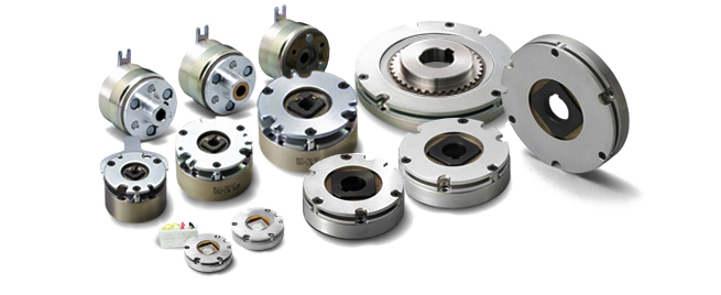
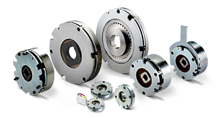
Electromagnetic clutches and brakes are devices that, as their names suggest, couple, release, brake and hold machinery in place using electromagnetic force generated by passing a current through a coil. They are divided into two types by their method of actuation: electromagnetic actuated and spring actuated. Electromagnetic actuated refers to clutches and brakes that are actuated when a current is passed through a coil; spring actuated refers to brakes that are actuated by the force of a spring when current to the coil is shut off, as happen in power outages. Miki Pulley divides its electromagnetic clutches and brakes into several major categories: electromagnetic-actuated clutches and brakes, spring-actuated brakes, electromagnetic tooth clutches, brake motors, and electromagnetic clutch and brake power supplies. We provide a particularly wide range of electromagnetic-actuated clutches and brakes, including models with large and small transmission torques and units that combine functionality. This enables us to supply the optimal product for your application.
ELECTROMAGNETIC CLUTCHES & BRAKES
Electromagnetic-actuated Micro Clutches and Brakes
These micro clutches and brakes are ideal for compact precision equipment where variations in torque and response must be avoided, such as office, communications, and automobile equipment.
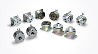
Electromagnetic-actuated Clutches and Brakes
These units provide excellent performance thanks to intelligent clutch and brake designs suited to the full range of general industrial machinery.
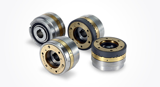
Electromagnetic Clutch and Brake Units
![]()
- 125 Models (Clutches and brakes) |
- 121-□-20G Types (Clutches and brakes) |
- 126 Models Clutch/Brake Units – Motor-coupled Type |
- CBW Models Clutch/ Brake Units – Speed Reducer-Integrated Type |
- CMW Models Clutch/Brake Units – Motor/Speed Reducer-Integrated Type |
- 121-□-10G Types (Double clutches) |
- 122 Models (Double clutches/brakes)
Select from our clutch and brake units to get the operation you require. It would be more convenient than when you combine as many clutches and brakes as you need.
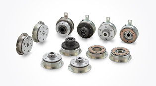
Spring-Actuated Brakes
These are electromagnetic brakes that are actuated by the force of a spring when electricity is not flowing. They are used for emergency braking when power goes out, for holding stopped positions for long periods of time, and the like.
Electromagnetic Toothed Clutches
These are electromagnetic-actuated clutches that transmit torque by engaging teeth. They are compact and can transmit very high torque.
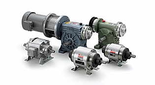
Brake Motors
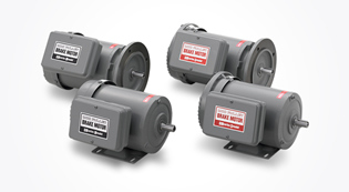
These products incorporate an internal electromagnetic-actuated brake or spring-actuated brake without changing the dimensions of the general-purpose motor.
Electromagnetic Clutch & Brake Power Supplies
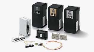
![]()
These are power supplies for getting the best performance from our electromagnetic clutch and brakes products. They are divided into high-speed control supplies and rectified supplies.
| Model | Size | Dynamic friction torque Td [N・m] | Coil (at 20℃) | Lead wire | Heat resistance class | Max. rotation speed [min-1] | Rotating part moment of inertia J | Allowable engaging work Eeaℓ [J] | Total work performed until readjustment of the air gap ET [J] | Armature pull-in time ta [s] | Torque rise time tp [s] | Torque extinction time td [s] | Mass [kg] | |||||
|---|---|---|---|---|---|---|---|---|---|---|---|---|---|---|---|---|---|---|
| Voltage [V] | Wattage [W] | Current [A] | Resistance [Ω] | UL style | Size | Armature [kg・m2] | Rotor [kg・m2] | |||||||||||
| 102-02-13 | 2 | 0.4 | DC24 | 6 | 0.25 | 96 | UL3398 | AWG26 | B | 10000 | 6.75×10⁻⁷ | 2.45×10⁻⁶ | 1500 | 2×10⁶ | 0.009 | 0.019 | 0.017 | 0.075 |
| 102-02-15 | 2 | 0.4 | DC24 | 6 | 0.25 | 96 | UL3398 | AWG26 | B | 500 | 1.00×10⁻⁶ | 2.45×10⁻⁶ | 1500 | 2×10⁶ | 0.009 | 0.019 | 0.017 | 0.081 |
| 102-02-11 | 2 | 0.4 | DC24 | 6 | 0.25 | 96 | UL3398 | AWG26 | B | 10000 | 1.00×10⁻⁶ | 2.45×10⁻⁶ | 1500 | 2×10⁶ | 0.009 | 0.019 | 0.017 | 0.079 |
| 102-03-13 | 3 | 0.6 | DC24 | 6 | 0.25 | 96 | UL3398 | AWG26 | B | 10000 | 1.30×10⁻⁶ | 3.25×10⁻⁶ | 2300 | 3×10⁶ | 0.009 | 0.022 | 0.02 | 0.096 |
| 102-03-15 | 3 | 0.6 | DC24 | 6 | 0.25 | 96 | UL3398 | AWG26 | B | 500 | 1.95×10⁻⁶ | 3.25×10⁻⁶ | 2300 | 3×10⁶ | 0.009 | 0.022 | 0.02 | 0.105 |
| 102-03-11 | 3 | 0.6 | DC24 | 6 | 0.25 | 96 | UL3398 | AWG26 | B | 10000 | 1.95×10⁻⁶ | 3.25×10⁻⁶ | 2300 | 3×10⁶ | 0.009 | 0.022 | 0.02 | 0.103 |
| 102-04-13 | 4 | 1.2 | DC24 | 8 | 0.33 | 72 | UL3398 | AWG26 | B | 10000 | 4.38×10⁻⁶ | 1.41×10⁻⁵ | 4500 | 6×10⁶ | 0.011 | 0.028 | 0.03 | 0.178 |
| 102-04-15 | 4 | 1.2 | DC24 | 8 | 0.33 | 72 | UL3398 | AWG26 | B | 500 | 6.15×10⁻⁶ | 1.41×10⁻⁵ | 4500 | 6×10⁶ | 0.011 | 0.028 | 0.03 | 0.195 |
| 102-04-11 | 4 | 1.2 | DC24 | 8 | 0.33 | 72 | UL3398 | AWG26 | B | 10000 | 6.15×10⁻⁶ | 1.41×10⁻⁵ | 4500 | 6×10⁶ | 0.011 | 0.028 | 0.03 | 0.191 |
| 102-05-13 | 5 | 2.4 | DC24 | 10 | 0.42 | 58 | UL3398 | AWG22 | B | 10000 | 9.08×10⁻⁶ | 3.15×10⁻⁵ | 9000 | 9×10⁶ | 0.012 | 0.031 | 0.04 | 0.31 |
| 102-05-15 | 5 | 2.4 | DC24 | 10 | 0.42 | 58 | UL3398 | AWG22 | B | 500 | 1.38×10⁻⁵ | 3.15×10⁻⁵ | 9000 | 9×10⁶ | 0.012 | 0.031 | 0.04 | 0.335 |
| 102-05-11 | 5 | 2.4 | DC24 | 10 | 0.42 | 58 | UL3398 | AWG22 | B | 10000 | 1.38×10⁻⁵ | 3.15×10⁻⁵ | 9000 | 9×10⁶ | 0.012 | 0.031 | 0.04 | 0.325 |
*The dynamic friction torque, Td, is measured at a relative speed of 100 min-1.
*The moment of inertia of a rotating body and mass are measured for the maximum bore diameter.
*Keep supply voltage fluctuation to within 10% of coil voltage.
[Dimensions]
102-□-13 (Direct mount-use)
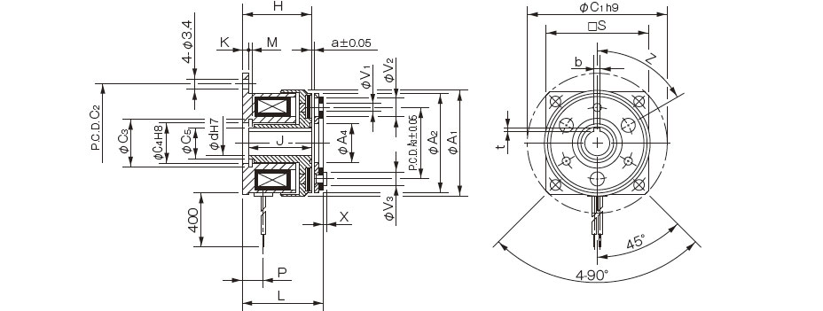
| Size | Radial direction dimensions | Axial direction dimensions | ||||||||||||||||||||
|---|---|---|---|---|---|---|---|---|---|---|---|---|---|---|---|---|---|---|---|---|---|---|
| A1 | A2 | A3 | A4 | C1 | C2 | C3 | C4 | C5 | S | V1 | V2 | V3 | Z | H | J | K | L | P | M | a | X | |
| 02 | 31 | 28 | 19.5 | 10.5 | 39 | 33.5 | 11.4 | 11 | 8 | - | 2-2.1 | 2-5.3 | 2-4 | 4-90° | 18 | 16.5 | 1.5 | 20.5 | 5 | 1.1 | 0.1 | 0.8 |
| 03 | 34 | 32 | 23 | 12.5 | 45 | 38 | 13.6 | 13 | 10 | 33 | 3-2.6 | 3-6 | 3-4.5 | 6-60° | 22.2 | 20.2 | 2 | 24.5 | 6.7 | 1.3 | 0.15 | 1.2 |
| 04 | 43 | 40 | 30 | 18.5 | 54 | 47 | 20 | 19 | 15.5 | 41 | 3-3.1 | 3-6 | 3-5 | 6-60° | 25.4 | 23.4 | 2 | 28.2 | 7 | 1.3 | 0.15 | 1.5 |
| 05 | 54 | 50 | 38 | 25.5 | 65 | 58 | 27.2 | 26 | 22 | 51 | 3-3.1 | 3-6.5 | 3-5.5 | 6-60° | 28.1 | 26.1 | 2 | 31.3 | 8.2 | 1.5 | 0.2 | 1.5 |
*Size 02 is a rounded flange.
*The rotor of size 02 has no keyway. Lock it in place by press-fitting it onto the shaft or the like.
| Size | Shaft bore dimensions | ||||
|---|---|---|---|---|---|
| d1 H7 | Models compliant with the new JIS standards | Models compliant with the old JIS standards | |||
| b P9 | t | b P9 | t | ||
| 02 | 5 | - | - | - | - |
| 03 | 6 | 2-0.006-0.031 | 0.8+0.30 | - | - |
| 04 | 8 | 2-0.006-0.031 | 0.8+0.30 | - | - |
| 10 | 3-0.006-0.031 | 1.2+0.30 | 4+0.050+0.020 | 1.5+0.50 | |
| 05 | 10 | 3-0.006-0.031 | 1.2+0.30 | 4+0.050+0.020 | 1.5+0.50 |
| 15 | 5-0.012-0.042 | 2+0.50 | 5+0.050+0.020 | 2+0.50 | |

[Dimensions]
102-□-15 (Through-shaft-use)
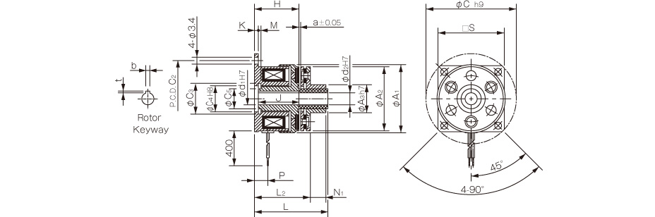
| Size | Radial direction dimensions | Axial direction dimensions | ||||||||||||||||
|---|---|---|---|---|---|---|---|---|---|---|---|---|---|---|---|---|---|---|
| A1 | A2 | A3 | C1 | C2 | C3 | C4 | C5 | S | H | J | K | L1 | L2 | M | P | N1 | a | |
| 02 | 31 | 28 | 13 | 39 | 33.5 | 11.4 | 11 | 8 | - | 18 | 16.5 | 1.5 | 27.5 | 22.4 | 1.1 | 5 | 4.8 | 0.1 |
| 03 | 34 | 32 | 14 | 45 | 38 | 13.6 | 13 | 10 | 33 | 22.2 | 20.2 | 2 | 34.5 | 26.5 | 1.3 | 6.7 | 7.8 | 0.15 |
| 04 | 43 | 40 | 18 | 54 | 47 | 20 | 19 | 15.5 | 41 | 25.4 | 23.4 | 2 | 40.2 | 30.8 | 1.3 | 7 | 9.1 | 0.15 |
| 05 | 54 | 50 | 28 | 65 | 58 | 27.2 | 26 | 22 | 51 | 28.1 | 26.1 | 2 | 43.3 | 34.3 | 1.5 | 8.2 | 8.8 | 0.2 |
*Size 02 is a rounded flange.
*The rotor of size 02 has no keyway. Lock it in place by press-fitting it onto the shaft or the like.
| Size | Shaft bore dimensions | |||||
|---|---|---|---|---|---|---|
| d1 H7 | d2 H7 | Models compliant with the new JIS standards | Models compliant with the old JIS standards | |||
| b P9 | t | b P9 | t | |||
| 02 | 5 | 5 | - | - | - | - |
| 03 | 6 | 6 | 2-0.006-0.031 | 0.8+0.30 | - | - |
| 04 | 8 | 8 | 2-0.006-0.031 | 0.8+0.30 | - | - |
| 10 | 10 | 3-0.006-0.031 | 1.2+0.30 | 4+0.050+0.020 | 1.5+0.50 | |
| 05 | 10 | 10 | 3-0.006-0.031 | 1.2+0.30 | 4+0.050+0.020 | 1.5+0.50 |
| 15 | 15 | 5-0.012-0.042 | 2+0.50 | 5+0.050+0.020 | 2+0.50 | |
*The armature type-5 bore d2 is a straight bore.
[Dimensions]
102-□-11 (Butt shaft-use)
| Size | Radial direction dimensions | Axial direction dimensions | ||||||||||||||||||
|---|---|---|---|---|---|---|---|---|---|---|---|---|---|---|---|---|---|---|---|---|
| A1 | A2 | A3 | C1 | C2 | C3 | C4 | C5 | S | m | H | J | K | L1 | L2 | M | P | U | T | a | |
| 02 | 31 | 28 | 9.5 | 39 | 33.5 | 11.4 | 11 | 8 | - | M3 | 18 | 16.5 | 1.5 | 27.5 | 22.5 | 1.1 | 5 | 7 | 2.5 | 0.1 |
| 03 | 34 | 32 | 12 | 45 | 38 | 13.6 | 13 | 10 | 33 | 2-M3 | 22.2 | 20.2 | 2 | 34.5 | 26.5 | 1.3 | 6.7 | 10 | 4 | 0.15 |
| 04 | 43 | 40 | 17 | 54 | 47 | 20 | 19 | 15.5 | 41 | 2-M3 | 25.4 | 23.4 | 2 | 40.2 | 30.8 | 1.3 | 7 | 12 | 5 | 0.15 |
| 05 | 54 | 50 | 24 | 65 | 58 | 27.2 | 26 | 22 | 51 | 2-M4 | 28.1 | 26.1 | 2 | 43.3 | 34.3 | 1.5 | 8.2 | 12 | 5 | 0.2 |
*Size 02 is a rounded flange.
*The rotor of size 02 has no keyway. Lock it in place by press-fitting it onto the shaft or the like.
| Size | Shaft bore dimensions | |||||
|---|---|---|---|---|---|---|
| d1 H7 | d2 H7 | Models compliant with the new JIS standards | Models compliant with the old JIS standards | |||
| b P9 | t | b P9 | t | |||
| 02 | 5 | 5 | - | - | - | - |
| 03 | 6 | 6 | 2-0.006-0.031 | 0.8+0.30 | - | - |
| 04 | 8 | 8 | 2-0.006-0.031 | 0.8+0.30 | - | - |
| 10 | 10 | 3-0.006-0.031 | 1.2+0.30 | 4+0.050+0.020 | 1.5+0.50 | |
| 05 | 10 | 10 | 3-0.006-0.031 | 1.2+0.30 | 4+0.050+0.020 | 1.5+0.50 |
| 15 | 15 | 5-0.012-0.042 | 2+0.50 | 5+0.050+0.020 | 2+0.50 | |
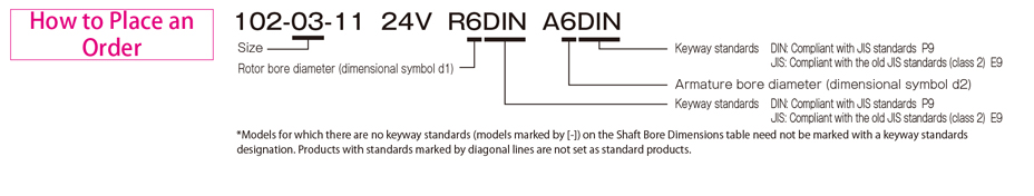
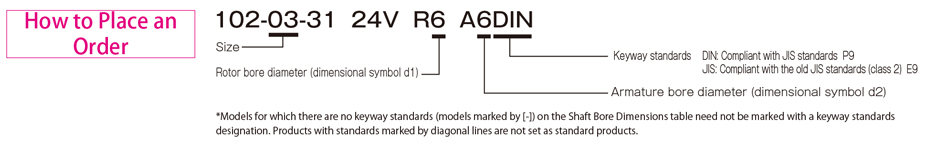
102-□-3□ Types
[Specifications]
| Model | Size | Dynamic friction torque Td [N・m] | Coil (at 20℃) | Lead wire | Heat resistance class | Max. rotation speed [min-1] | Rotating part moment of inertia J | Allowable engaging energy Eeaℓ [J] | Total work performed until readjustment of the air gap ET [J] | Armature suction time ta [s] | Torque rise time tp [s] | Torque extinction time td [s] | Mass [kg] | |||||
|---|---|---|---|---|---|---|---|---|---|---|---|---|---|---|---|---|---|---|
| Voltage [V] | Wattage [W] | Current [A] | Resistance [Ω] | UL style | Size | Armature [kg・m2] | Rotor [kg・m2] | |||||||||||
| 102-02-33 | 2 | 0.4 | DC24 | 6 | 0.25 | 96 | UL3398 | AWG26 | B | 500 | 6.75×10⁻⁷ | 2.75×10⁻⁶ | 1500 | 2×10⁶ | 0.009 | 0.019 | 0.017 | 0.076 |
| 102-02-35 | 2 | 0.4 | DC24 | 6 | 0.25 | 96 | UL3398 | AWG26 | B | 500 | 1.00×10⁻⁶ | 2.75×10⁻⁶ | 1500 | 2×10⁶ | 0.009 | 0.019 | 0.017 | 0.082 |
| 102-02-31 | 2 | 0.4 | DC24 | 6 | 0.25 | 96 | UL3398 | AWG26 | B | 500 | 1.00×10⁻⁶ | 2.75×10⁻⁶ | 1500 | 2×10⁶ | 0.009 | 0.019 | 0.017 | 0.08 |
| 102-03-33 | 3 | 0.6 | DC24 | 6 | 0.25 | 96 | UL3398 | AWG26 | B | 500 | 1.30×10⁻⁶ | 4.08×10⁻⁶ | 2300 | 3×10⁶ | 0.009 | 0.022 | 0.02 | 0.101 |
| 102-03-35 | 3 | 0.6 | DC24 | 6 | 0.25 | 96 | UL3398 | AWG26 | B | 500 | 1.95×10⁻⁶ | 4.08×10⁻⁶ | 2300 | 3×10⁶ | 0.009 | 0.022 | 0.02 | 0.11 |
| 102-03-31 | 3 | 0.6 | DC24 | 6 | 0.25 | 96 | UL3398 | AWG26 | B | 500 | 1.95×10⁻⁶ | 4.08×10⁻⁶ | 2300 | 3×10⁶ | 0.009 | 0.022 | 0.02 | 0.108 |
| 102-04-33 | 4 | 1.2 | DC24 | 8 | 0.33 | 72 | UL3398 | AWG26 | B | 500 | 4.38×10⁻⁶ | 1.44×10⁻⁵ | 4500 | 6×10⁶ | 0.011 | 0.028 | 0.03 | 0.183 |
| 102-04-35 | 4 | 1.2 | DC24 | 8 | 0.33 | 72 | UL3398 | AWG26 | B | 500 | 6.15×10⁻⁶ | 1.44×10⁻⁵ | 4500 | 6×10⁶ | 0.011 | 0.028 | 0.03 | 0.2 |
| 102-04-31 | 4 | 1.2 | DC24 | 8 | 0.33 | 72 | UL3398 | AWG26 | B | 500 | 6.15×10⁻⁶ | 1.44×10⁻⁵ | 4500 | 6×10⁶ | 0.011 | 0.028 | 0.03 | 0.196 |
| 102-05-33 | 5 | 2.4 | DC24 | 10 | 0.42 | 58 | UL3398 | AWG22 | B | 500 | 9.08×10⁻⁶ | 2.90×10⁻⁵ | 9000 | 9×10⁶ | 0.012 | 0.031 | 0.04 | 0.321 |
| 102-05-35 | 5 | 2.4 | DC24 | 10 | 0.42 | 58 | UL3398 | AWG22 | B | 500 | 1.38×10⁻⁵ | 2.90×10⁻⁵ | 9000 | 9×10⁶ | 0.012 | 0.031 | 0.04 | 0.346 |
| 102-05-31 | 5 | 2.4 | DC24 | 10 | 0.42 | 58 | UL3398 | AWG22 | B | 500 | 1.38×10⁻⁵ | 2.90×10⁻⁵ | 9000 | 9×10⁶ | 0.012 | 0.031 | 0.04 | 0.336 |
*The dynamic friction torque, Td, is measured at a relative speed of 100 min-1.
*The moment of inertia of a rotating body and mass are measured for the maximum bore diameter.
*Keep supply voltage fluctuation to within 10% of coil voltage.
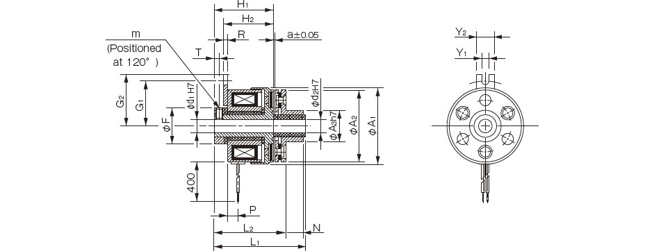
[Dimensions]
102-□-33 (Direct mount-use)
| Size | Radial direction dimensions | Axial direction dimensions | ||||||||||||||||||||
|---|---|---|---|---|---|---|---|---|---|---|---|---|---|---|---|---|---|---|---|---|---|---|
| A1 | A2 | A3 | A4 | F | V1 | V2 | V3 | G1 | G2 | Y1 | Y2 | Z | m | H | R | L1 | L2 | P | N | T | a | |
| 02 | 31 | 28 | 19.5 | 10.5 | 14 | 2-2.1 | 2-5.3 | 2-4 | 15.8 | 19.8 | 3.1 | 8 | 4-90° | 2-M3 | 19.1 | 1.6 | 25.9 | 23.5 | 4.7 | 0.8 | 2.5 | 0.1 |
| 03 | 34 | 32 | 23 | 12.5 | 16 | 3-2.6 | 3-6 | 3-4.5 | 20 | 23 | 3.1 | 8 | 6-60° | 2-M3 | 21.8 | 1.6 | 28.5 | 26.2 | 4.7 | 1.2 | 2.3 | 0.15 |
| 04 | 43 | 40 | 30 | 18.5 | 22 | 3-3.1 | 3-6 | 3-5 | 23 | 26 | 3.1 | 8 | 6-60° | 2-M4 | 25 | 1.6 | 33.2 | 30.4 | 5.2 | 1.5 | 2.8 | 0.15 |
| 05 | 54 | 50 | 38 | 25.5 | 30 | 3-3.1 | 3-6.5 | 3-5.5 | 28 | 31 | 3.1 | 8 | 6-60° | 2-M5 | 27.9 | 1.6 | 37.3 | 34.1 | 6.2 | 1.5 | 3.3 | 0.2 |
| Size | Shaft bore dimensions |
|---|---|
| d1 H7 | |
| 02 | 5 |
| 03 | 6 |
| 04 | 8 |
| 10 | |
| 05 | 10 |
| 15 |

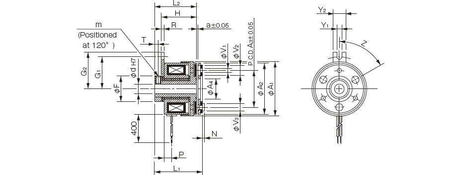
[Dimensions]
102-□-35 (Through-shaft-use)
| Size | Radial direction dimensions | Axial direction dimensions | ||||||||||||||||
|---|---|---|---|---|---|---|---|---|---|---|---|---|---|---|---|---|---|---|
| A1 | A2 | A3 | F | G1 | G2 | Y1 | Y2 | m | H1 | H2 | R | L1 | L2 | P | N | T | a | |
| 02 | 31 | 28 | 13 | 14 | 15.8 | 20 | 3.1 | 8 | 2-M3 | 23.5 | 19.5 | 1.6 | 33 | 27.9 | 4.7 | 4.8 | 2.5 | 0.1 |
| 03 | 34 | 32 | 14 | 16 | 20 | 23 | 3.1 | 8 | 2-M3 | 26.2 | 21.9 | 1.6 | 38.5 | 30.5 | 4.7 | 7.8 | 2.3 | 0.15 |
| 04 | 43 | 40 | 18 | 22 | 23 | 26 | 3.1 | 8 | 2-M4 | 30.4 | 25.1 | 1.6 | 45.2 | 35.8 | 5.2 | 9.1 | 2.8 | 0.15 |
| 05 | 54 | 50 | 28 | 30 | 28 | 31 | 3.1 | 8 | 2-M5 | 34.1 | 27.9 | 1.6 | 49.3 | 0.3 | 6.2 | 8.8 | 3.3 | 0.2 |
| Size | Shaft bore dimensions | |
|---|---|---|
| d1 H7 | d2 H7 | |
| 02 | 5 | 5 |
| 03 | 6 | 6 |
| 04 | 8 | 8 |
| 10 | 10 | |
| 05 | 10 | 10 |
| 15 | 15 | |

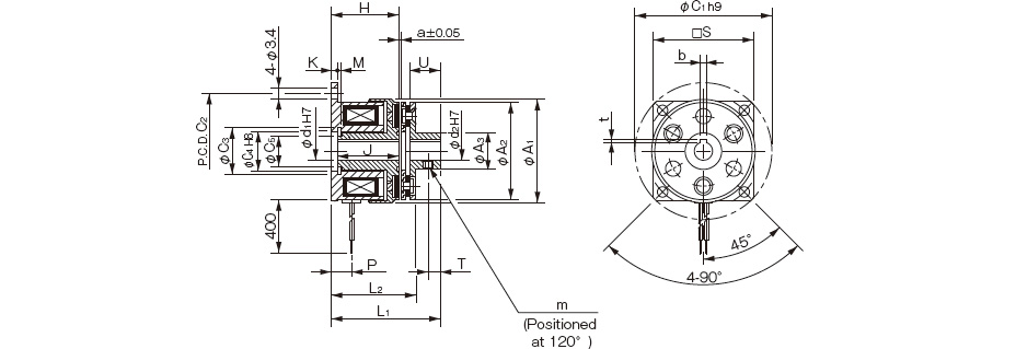
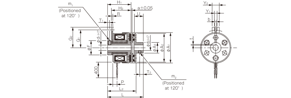
[Dimensions]
102-□-31 (Butt shaft-use)
| Size | Radial direction dimensions | Axial direction dimensions | ||||||||||||||||||
|---|---|---|---|---|---|---|---|---|---|---|---|---|---|---|---|---|---|---|---|---|
| A1 | A2 | A3 | F | G1 | G2 | Y1 | Y2 | m1 | m2 | H1 | H2 | R | L1 | L2 | P | U | T1 | T2 | a | |
| 02 | 31 | 28 | 9.5 | 14 | 15.8 | 20 | 3.1 | 8 | 2-M3 | M3 | 23.5 | 19.5 | 1.6 | 33 | 27.9 | 4.7 | 7 | 2.5 | 2.5 | 0.1 |
| 03 | 34 | 32 | 12 | 16 | 20 | 23 | 3.1 | 8 | 2-M3 | 2-M3 | 26.2 | 21.9 | 1.6 | 38.5 | 30.5 | 4.7 | 10 | 2.3 | 4 | 0.15 |
| 04 | 43 | 40 | 17 | 22 | 23 | 26 | 3.1 | 8 | 2-M4 | 2-M3 | 30.4 | 25.1 | 1.6 | 45.2 | 35.8 | 5.2 | 12 | 2.8 | 5 | 0.15 |
| 05 | 54 | 50 | 24 | 30 | 28 | 31 | 3.1 | 8 | 2-M5 | 2-M4 | 34.1 | 27.9 | 1.6 | 49.3 | 40.3 | 6.2 | 12 | 3.3 | 5 | 0.2 |
| Size | Shaft bore dimensions | |||||
|---|---|---|---|---|---|---|
| d1 H7 | d2 H7 | Models compliant with the new JIS standards | Models compliant with the old JIS standards | |||
| b P9 | t | b P9 | t | |||
| 02 | 5 | 5 | - | - | - | - |
| 03 | 6 | 6 | 2-0.006-0.031 | 0.8+0.30 | - | - |
| 04 | 8 | 8 | 2-0.006-0.031 | 0.8+0.30 | - | - |
| 10 | 10 | 3-0.006-0.031 | 1.2+0.30 | 4+0.050+0.020 | 1.5+0.50 | |
| 05 | 10 | 10 | 3-0.006-0.031 | 1.2+0.30 | 4+0.050+0.020 | 1.5+0.50 |
| 15 | 15 | 5-0.012-0.042 | 2+0.50 | 5+0.050+0.020 | 2+0.50 | |

/5
Dựa trên đánh giá
Đánh giá
Chưa có đánh giá nào.