
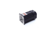
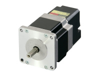
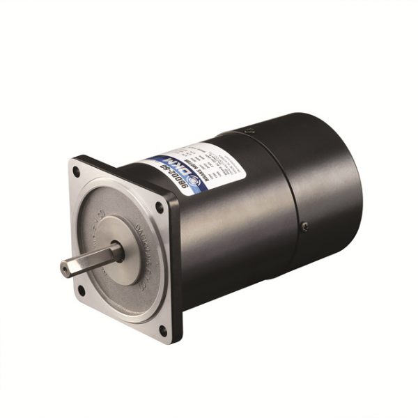
Motor Excem tại Bình Dương
Liên hệ
Chúng tôi là nhà phân phối chính thức các sản phẩm của EXCEM tại thị trường Việt Nam, Quý khách có nhu cầu về các sản phẩm của EXCEM vui lòng liên hệ trực tiếp với chúng tôi để được tư vấn nhanh hơn.
Hotline: 0974190088/Zalo
Email: vuonguoc@gmail.com
Motor Excem tại Bình Dương


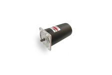
DC Geared Motor
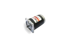
DC Geared Motor
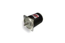
DC Geared Motor

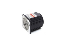
DC Geared Motor

DC Geared Motor

DC Geared Motor

DC Geared Motor

DC Geared Motor

DC Geared Motor

DC Geared Motor

DC Geared Motor

DC Geared Motor

DC Geared Motor

DC Geared Motor

DC Geared Motor

DC Geared Motor

DC Geared Motor

DC Geared Motor

DC Geared Motor

DC Geared Motor

DC Geared Motor

DC Geared Motor

DC Geared Motor

DC Geared Motor

DC Geared Motor

DC Geared Motor

DC Geared Motor

DC Geared Motor

DC Geared Motor

DC GearHead

DC GearHead

DC GearHead

DC GearHead (Powerful Gearhead)

DC GearHead (Hi Powerful Gearhead)

DC GearHead (90mm Decimal Gearhead)

DC Special Motor

Ø50 Motor for vacuum cleaner

DC Special Motor

Side shaft for air compressor

DC Special Motor

DC Special Motor

DC Special Motor

DC Special Motor

DC Special Motor

DC Special Motor

DC Special Motor

DC Special Motor

DC Special Motor

DC Special Motor

DC Special Motor
DC Special Motor (DC Motor 4pole)

DC Special Motor

DC Special Motor (60mm Planetary Gearhead)

DC Special Motor (with Planetary Gearhead)

DC Special Motor (Ø50 motor for massager)

Brushless DC Motor (220V 40W/50W 80mm)

Brushless DC Motor (220V 90W/100W 90mm)

Brushless DC Motor (24V 100W 90mm)

Brushless DC Motor (220V 20W/30W 60mm)

Brushless DC Motor (24V 30W 60mm)

Brushless DC Motor (24V 50W 80mm)

BLDC GearHead (60mm)

BLDC GearHead (90mm)

BLDC GearHead (80mm)

BLDC Driver

BLDC Driver

Automatic Door Control System

BLDC Motor with Electromagnetic Brake

BLDC Motor (Explosion-Proof type)

BLDC Special Motor

BLDC Special Motor

Induction Motor (6W, 1/124 HP)

Induction Motor (15W, 1/50 HP)
Induction Motor (25W, 1/30 HP)

Induction Motor (40W, 1/18.5 HP)

Induction Motor (60W, 1/12.5 HP)

Induction Motor (90W, 1/8 HP)

Induction Motor (120W, 1/6 HP)
Induction Motor (180W, 1/4 HP)

Induction Motor (200W, 1/3.7 HP)
Một số model bán chạy năm 2010.2011.2012.2013:
DAEHWA E/M CO.,LTD.
CONTROLLER SERIES
180 CONTROLLERS
ESA-U SERIES CONTROLLER
UNIT TYPE
– Speed Controller with Tacho generator
– Digital Type : PI Automatic Control by MICOM
– One-touch connection by 8 pin housing
connector
(extension cord 3[m] long max, optional)
– Built-in speed setting
Features
- Turn on the main circuit breaker.
- Turn on the RUN/STOP switch.
- Turn “Speed Control Knob” slowly, clockwise, to increase speed.
- Turn “Speed Control Knob” slowly, counter clockwise, to decrease speed.
- Turn off the RUN/STOP switch to stop the motor
* No.1 and No.2 of TERMINAL BLOCK can use as rpm meter
Operation
181
CONTROLLERS
ESA-U SERIES CONTROLLERS
UNIT TYPE
* CW
and connection(short)
* CCW
and connection(short)
Motor & Controller Connection
Cut a hole in the mounting plate as indicated in the diagram to the left.
Insert the control unit from the front of the mounting
plate and fasten with screws and nuts.
Mounting screw(M4 10) 2
Nuts 2
Washers 2
Changing the motor’s rotation “CW”(set at the factory) to “CCW”
Connection
Installation
182 CONTROLLERS
ESA-U SERIES CONTROLLERS
UNIT TYPE
Dimensions
Performance Data
Unit : mm(inch)
1 Input voltage 1 Ph. 100V 1 Ph. 200V 1 Ph. 115V 1 Ph. 220V 1 Ph. 220V~240V
2 Input voltage Threshold Rated voltage 10%
3 Input Frequency 50 / 60 Hz
4 Speed Range 50Hz : 90~1400 rpm, 60Hz : 90~1700rpm
5 Permissible Current MAX. 5A
6 Motor output 6W ~ 180 W
7 Control method TRIAC AC PHASE CONTROL
8 Speed Control method PI Automatic Control by MICOM
9 Sensor Type AC Tacho Generator(T.G)
10 Speed set method Volume type
11 Power switch Tumbler switch
12 Display Red LED Input Power ON : light, Input Power OFF : off
13 Weight About 170g(Except for Internal Capacitor)
14 Operating Temp. -5° ~ +40°
15 Operating Humidity Max 85% (No condensation)
16 FUSE Inside control unit
17 Insulation Resistance
100M or more when 500VDC is applied
between the windings and the frame
18 Dielectric Strength
Sufficient to withstand 1.5kV at 50/60Hz applied between the
windings and the frame for 1 minute
19 EMC Please contact us
Model
ESA-U
Item
183
CONTROLLERS
ESA-U SERIES CONTROLLERS
UNIT TYPE
Extension Cord
Extension cord(optional) is conveniently used when motor is located more than 300[mm]
apart from control unit
Standard length is 0.5[m]
(option : max 3[m])
184 CONTROLLERS
The rotation speed of motor can be changed by controller
In case that the T.G’s wire is long, please connect
double twist sealed wire (Please, Don’t connect double
twist shield wire to earth)
In case of induction motor please connect to method of
dotted line
Wiring of the fan is for motors 60 watts and over.
Control Pack
8 Pin Socket
SPEED CONTROL VOLUME
Name Plate
Function Identification
Basic Wiring diagram
ESA-P SERIES CONTROLLERS
PLUG-IN TYPE
– Speed Controller with Tacho generator
– Plug-in type for standard 8 pin socket
– Built-in speed setting(external speed setting applicable)
– Instantaneous stop by electric brake circuit
– Various application
Features
185
CONTROLLERS
ESA-P SERIES CONTROLLERS
PLUG-IN TYPE
Dimensions
Unit : mm(inch)
Performance Data
1 Input voltage 1 Ph. 100V 1 Ph. 200V 1 Ph. 115V 1 Ph. 220V 1 Ph. 220V~240V
2 Input voltage Threshold Rated voltage 10%
3 Input Frequency 50 / 60 Hz
4 Speed Range 50Hz : 90~1400 rpm, 60Hz : 90~1700rpm
5 Motor output 6W ~ 180 W
6 Control method TRIAC AC PHASE CONTROL
7 Speed Control method PI Automatic Control by MICOM
8 Sensor Type AC Tacho Generator(T.G)
9 Speed set method Volume type(With external speed setting device optional)
10 Brake Run electric brake for certain period to motor
11 Electric Brake Time 0.5sec. (Average)
12 Slow Run, Slow Stop None
13 Operating Temp. -5° ~ +40°
14 Operating Humidity Max 85% (No condensation)
Model
ESA-V
Item
186
ESA-P SERIES CONTROLLERS
PLUG-IN TYPE
BASIC CONNECTION DIAGRAM
S/W 1 AC 125[V] or AC 250[V] Min. 5A
Induction Motor(Continuous Duty) 4 Lead wire type
Single Direction+Variable Speed(6W~120W)
Single Direction + Variable Speed + Electric Brake(6W~25W)
Single Direction + Variable Speed + Electric Brake(40W~120W)
– The motor rotating direction is CW when viewed from
shaft side if connected like the solid line of above
diagram.
– When adjusting to CCW direction, change and connect
blue and red wire of motor.
– The wiring of fan motor is applicable for motors 60W
and over.
S/W 1, S/W 2
S/W 3
R0
C0
R1
AC 125[V] or AC 250[V] Min. 5A
DC 10[V] 10[mA]
10 ~ 200[ ] Min. 1/4 [W]
0.1 ~ 0.33[ ]
(AC 125 [V]or AC 250[V])
5.6 [ ] Min. 10[W]
– The motor rotating direction is CW when viewed from
shaft side if connected like the solid line of above
diagram.
– When adjusting to CCW direction, change and connect
blue and red wire of motor.
– When changing from RUN to STOP, the control brake
willfunction for 0.5sec and the motor stops immediately.
– The wiring of fan motor is applicable for motors 60W and
over.
S/W 1, S/W 2
S/W 3
R0
C0
R1
AC 125[V] or AC 250[V] Min. 5A
DC 10[V] 10[mA]
10 ~ 200[ ] Min. 1/4 [W]
0.1 ~ 0.33[ ]
(AC 125 [V]or AC 250[V])
5.6 [ ] Min. 10[W]
– The motor rotating direction is CW when viewed from
shaft side if connected like the solid line of above
diagram.
– When adjusting to CCW direction, change and connect
blue and red wire of motor.
– When changing from RUN to STOP, the control brake
willfunction for 0.5sec and the motor stops immediately.
CONTROLLERS
187
ESA-P SERIES CONTROLLERS
PLUG-IN TYPE
BASIC CONNECTION DIAGRAM
S/W 1, S/W 2 AC 125[V] or AC 250[V] Min. 5A
Induction(3 Lead wire type) & Reversible Motor(30min. Duty)
Reverse + Variable Speed(6W~120W)
Reverse + Variable Speed + Electric Brake(6W~25W)
– Change to S/W2 after a certain period of stop for motor
– The wiring of fan motor is applicable for motors 60W and
over.
– Induction Motor(3 Lead wire type) – Continuous duty
S/W 1, S/W 2
S/W 4, S/W5
S/W 3
R0
C0
R1
AC 125[V] or AC 250[V] Min. 5A
DC 10[V] 10[mA]
10 ~ 200[ ] Min. 1/4 [W]
0.1 ~ 0.33[ ]
(AC 125 [V]or AC 250[V])
5.6 [ ] Min. 10[W]
– When stopped from running the electric brake will
function for 0.5sec and the motor stops immediately.
– During this 0.5sec, do not operate S/W4 or S/W5.
– Before S/W2 and S/W3 is switched to run, stop S/W2 and
S/W3 and than convert S/W4 and S/W5.
Reverse + Variable Speed + Electric Brake(40W~120W) S/W 1, S/W 2
S/W 4, S/W5
S/W 3
R0
C0
R1
AC 125[V] or AC 250[V] Min. 5A
DC 10[V] 10[mA]
10 ~ 200[ ] Min. 1/4 [W]
0.1 ~ 0.33[ ]
(AC 125 [V]or AC 250[V])
5.6 [ ] Min. 10[W]
– When stopped from running the electric brake will
function for 0.5sec and the motor stops immediately.
– During this 0.5sec, do not operate S/W4 or S/W5.
– Before S/W2 and S/W3 is switched to run, stop S/W2 and
S/W3 and than convert S/W4 and S/W5.
– The wiring of fan motor is applicable for motors 60W and
over.
CONTROLLERS
188
ESA-P SERIES CONTROLLERS
PLUG-IN TYPE
CONTROLLERS
APPLICATION CONNECTION DIAGRAM
VR
External speed setting device
20[ ] 1/4W B Type
The following is the explanations of external speed setting device
When long distance control is needed
When multi-stage speed setting is needed
– No.3 terminal of VR is not used.
– Set the controller scale to ‘0’.
– Wire connection should be in short distance.
Otherwise may cause malfunction.
– Use twisted sealed wire.
VR1, VR2,
VR3
S/W 3
External speed setting device
20[ ] 1/4W B Type
DC 10[V] 10[mA]
– Set the controller scale to ‘0’.
– Change the speed with external speed setting device
VR1,VR2 and VR3 by using S/W3.
– Wire connection should be in short distance.
Otherwise may cause malfunction.
– Use twisted sealed wire.
189
ESA-P SERIES CONTROLLERS
PLUG-IN TYPE
CONTROLLERS
SPEED CONTROL & BRAKE REVERSIBLE MOTOR CONNECTION DIAGRAM
When electric brake of controller is used simultaneously
Reverse + Variable Speed + Electric Brake + Electro magnetic brake motor (6W ~25W)
S/W 1, S/W 2
S/W 4, S/W5, S/W6
S/W 3
R0
C0
R1
AC 125[V] or AC 250[V] Min. 5A
DC 10[V] 10[mA]
10 ~ 200[ ] Min. 1/4 [W]
0.1 ~ 0.33[ ]
(AC 125 [V]or AC 250[V])
5.6 [ ] Min. 10[W]
– When changing from RUN to BRAKE the electric brake
operates and the motor stops immediately.
– Operate S/W4 and S/W5 after motor stops.
– Before switching S/W2, S/W3 and S/W6 from BRAKE to
RUN. Please convert S/W4 and S/W5 first.
– The power source S/W1 should be switched 0.5sec faster
than the operation starting signal of S/W2, S/W3 and
S/W6.
– When operating RUN-BRAKE, leave the S/W1 on, and
operate with S/W2, S/W3 and S/W6.
Reverse+Variable Speed+Electric Brake+Electro magnetic brake motor(40W+120W)
S/W 1, S/W 2
S/W 4, S/W5, S/W6
S/W 3
R0
C0
R1
AC 125[V] or AC 250[V] Min. 5A
DC 10[V] 10[mA]
10 ~ 200[ ] Min. 1/4 [W]
0.1 ~ 0.33[ ]
(AC 125 [V]or AC 250[V])
5.6 [ ] Min. 10[W]
– When changing from RUN to BRAKE the electric brake
operates and the motor stops immediately.
– Operate S/W4 and S/W5 after motor stops.
– Before switching S/W2, S/W3 and S/W6 from BRAKE to
RUN. Please convert S/W4 and S/W5 first.
– The power source S/W1 should be switched 0.5sec faster
than the operation starting signal of S/W2, S/W3 and
S/W6.
– When operating RUN-BRAKE, leave the S/W1 on, and
operate with S/W2, S/W3 and S/W6.
– The wiring of fan motor is applicable for motors 60W and
over.
190 CONTROLLERS
ESA-P SERIES CONTROLLERS
PLUG-IN TYPE
S/W 1, S/W 2
S/W 3
R0
C0
AC 125[V] or AC 250[V] Min. 5A
DC 10[V] 10[mA]
10 ~ 200[ ] Min. 1/4 [W]
0.1 ~ 0.33[ ]
(AC 125 [V]or AC 250[V])
– Leave a certain period until the motor stops, than switch
S/W2.
– The power source S/W1 should be switched 0.5sec faster
than the operation starting signal of S/W3 and S/W4.
– When operating RUN-STOP, leave the S/W1 ‘ON’, and
control with S/W3 and S/W4.
– Set the controller scale to ‘0’.
– The wiring of fan motor is applicable for motors 60W and
over.
SPEED CONTROL & BRAKE REVERSIBLE MOTOR CONNECTION DIAGRAM
When electric brake of controller is used simultaneously
Reverse + Variable Speed + Electro magnetic brake motor (6W ~120W)
Sản phẩm tương tự
-
Motor Oriental tại Đồng Nai
Liên hệ -
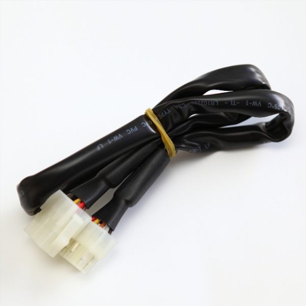
Extension Cable
Liên hệ -
Motor dkm tại Hải Dương
Liên hệ


/5
Dựa trên đánh giá
Đánh giá
Chưa có đánh giá nào.