
E9I90
Liên hệ
Chúng tôi là nhà phân phối chính thức các sản phẩm của EXCEM tại thị trường Việt Nam, Quý khách có nhu cầu về các sản phẩm của EXCEM vui lòng liên hệ trực tiếp với chúng tôi để được tư vấn nhanh hơn.
Hotline: 0974190088/Zalo
Email: vuonguoc@gmail.com
E9I90
Download tài liệu theo file sau:

Một số model bán chạy năm 2011.2012.2013:
DAEHWA E/M CO.,LTD.
INDUCTION MOTORS
6W (1/124 HP) INDUCTION MOTORS
Frame size 61mm sq. (2.4 in.sq.) Single-Phase LEAD WIRE TYPE
26 INDUCTION MOTORS
DIMENSIONS SPEED-TORQUE CURVE
Unit : mm(inch)
E6I6P L
E6I6D
Single phase E6I6
SPECIFICATIONS
CONTINUOUS DUTY, INSULATION CLASS A or E, 4POLES
Output Voltage Frequency Rated Starting Torque Capacitor
Model Input Current Torque Speed
(HP) (W) (V) (Hz) (W) (A) (kg-cm) (N-m) (oz-in) (rpm) (kg-cm) (N-m) (oz-in) ( )
E6I6 C 1/124 6 1100 50 23 0.22 0.47 0.046 6.53 1250 0.46 0.045 6.39 3
60 23 0.2 0.38 0.037 5.28 1550 0.46 0.045 6.39
E6I6 D 1/124 6 1200 50 23 0.11 0.47 0.046 6.53 1250 0.46 0.045 6.39
0.8
60 23 0.11 0.38 0.037 5.28 1550 0.46 0.045 6.39
E6I6 B 1/124 6 1220 60 30 0.12 0.38 0.037 5.28 1550 0.47 0.046 6.53 0.7
E6I6 E 1/124 6 1115 60 30 0.22 0.38 0.037 5.28 1550 0.45 0.044 6.25 2.5
E6I6 X 1/124 6 1220~240 50 30 0.12 0.47 0.046 6.53 1250 0.45 0.044 6.25 0.7
Model in grey screen represents the motors with IMPEDANCE PROTECTED according to UL regulation.
Model in dark grey screen represents the motors with IMPEDANCE PROTECTED according to CE regulation.
In case of some models certificated for export, the special cord like CE or UL is added after the existing model no. ex) E9I60 XH-CE, E9I60 EH-UL.
Insulation class for motors which acquired certificates for export is B.
CONNECTION DIAGRAMS (4-lead wire type)
CONNECTION DIAGRAMS (3-lead wire type)
GEARHEADS
Frame size 61mm sq. (2.4 in.sq.) METAL TYPE & BALL BEARING TYPE
27
INDUCTION MOTORS
DIMENSIONS
Unit : mm(inch)
E6G10D E6HD M(B)
E6HD M(B) + E6I6P L
RATED TORQUE OF GEARHEAD
E6HD M
kg-cm 1.1 1.9 2.9 4.8 5.7 8.6 10.3 15.5 23.3 30 30 30
E6HD B
N-m 0.11 0.19 0.28 0.47 0.56 0.84 1.01 1.52 2.28 2.94 2.94 2.94
oz-in 16 26 40 66 79 119 143 215 323 417 417 417
Speed(rpm) 500 300 200 120 100 60 50 30 20 15 10 9
MODEL
Ratio
50Hz 3 5 7.5 12.5 15 25 30 50 75 100 150 166.7
60Hz 3.6 6 9 15 18 30 36 60 90 120 180 200
The normal torque is that the motor and gearhead are directly coupled.
Insert the denominator of reduction ratio in of gearhead model name.
Actual rotation speed is 2~15% less than synchronous speed.
Color indicates that the rotation of gearhead shaft is in opposite direction as output shaft of motor.
DECIMAL GEARHEAD GEARHEAD
15W (1/50 HP) INDUCTION MOTORS
Frame size 70mm sq. (2.76 in.sq.) Single-Phase LEAD WIRE TYPE
28 INDUCTION MOTORS
DIMENSIONS SPEED-TORQUE CURVE
Unit : mm(inch)
Output Voltage Frequency Rated Starting Torque Capacitor
Model Input Current Torque Speed
(HP) (W) (V) (Hz) (W) (A) (kg-cm) (N-m) (oz-in) (rpm) (kg-cm) (N-m) (oz-in) ( )
E7I15 C 1/50 15 1100 50 45 0.4 1.17 0.115 16.25 1250 0.8 0.078 11.11
4
60 45 0.37 0.95 0.093 13.19 1550 0.8 0.078 11.11
E7I15 D 1/50 15 1200 50 45 0.2 1.17 0.115 16.25 1250 1 0.098 13.89
1.8
60 45 0.2 0.95 0.093 13.19 1550 1 0.098 13.89
E7I15 B 1/50 15 1220 60 45 0.2 0.95 0.093 13.19 1550 1.1 0.108 15.28 1.2
E7I15 E 1/50 15 1115 60 45 0.4 0.95 0.093 13.19 1550 1 0.098 13.89 4
E7I15 X 1/50 15 1220~240 50 45 0.19 1.17 0.115 16.25 1250 0.9 0.088 12.50 1.5
Model in grey screen represents the motors with THERMALLY PROTECTED according to UL regulation.
Model in dark grey screen represents the motors with THERMALLY PROTECTED according to CE regulation.
In case of some models certificated for export, the special cord like CE or UL is added after the existing model no. ex) E9I60 XH-CE, E9I60 EH-UL.
Insulation class for motors which acquired certificates for export is B.
E7I15P L
E7I15D
Single phase E7I15
SPECIFICATIONS
CONTINUOUS DUTY, INSULATION CLASS A or E, 4POLES
CONNECTION DIAGRAMS (4-lead wire type)
CONNECTION DIAGRAMS (3-lead wire type)
GEARHEADS
Frame size 70mm sq. (2.76 in.sq.) METAL TYPE & BALL BEARING TYPE
29
INDUCTION MOTORS
DIMENSIONS
Unit : mm(inch)
E7HK M
kg-cm 2.8 4.7 7.1 11.8 14.2 21.4 25.6 38.6 50 50 50 50
E7HK B
N-m 0.28 0.46 0.7 1.16 1.39 2.09 2.51 3.78 4.9 4.9 4.9 4.9
oz-in 39 66 99 165 197 297 356 536 694 694 694 694
Speed(rpm) 500 300 200 120 100 60 50 30 20 15 10 9
MODEL
Ratio
50Hz 3 5 7.5 12.5 15 25 30 50 75 100 150 166.7
60Hz 3.6 6 9 15 18 30 36 60 90 120 180 200
The normal torque is that the motor and gearhead are directly coupled.
Insert the denominator of reduction ratio in of gearhead model name.
Actual rotation speed is 2~15% less than synchronous speed.
Color indicates that the rotation of gearhead shaft is in opposite direction as output shaft of motor.
E7HK M(B)
E7HK M(B) + E7I15P L
RATED TORQUE OF GEARHEAD
E7G10D
DECIMAL GEARHEAD GEARHEAD
25W (1/30 HP) INDUCTION MOTORS
Frame size 80mm sq. (3.15 in. sq.) Single-Phase, Three-Phase LEAD WIRE TYPE
30 INDUCTION MOTORS
DIMENSIONS SPEED-TORQUE CURVE
Unit : mm(inch)
E8I25P L Single phase E8I25
E8I25D Three phase E8I25
Output Voltage Frequency Rated Starting Torque Capacitor
Model Input Current Torque Speed
(HP) (W) (V) (Hz) (W) (A) (kg-cm) (N-m) (oz-in) (rpm) (kg-cm) (N-m) (oz-in) ( )
E8I25 C 1/30 25 1100 50 60 0.57 1.95 0.191 27.08 1250 1.25 0.123 17.36 6
60 60 0.52 1.6 0.157 22.22 1550 1.25 0.123 17.36
E8I25 D 1/30 25 1200 50 60 0.28 1.95 0.191 27.08 1250 1.45 0.142 20.14 1.8
60 60 0.28 1.6 0.157 22.22 1550 1.45 0.142 20.14
E8I25 B 1/30 25 1220 60 65 0.3 1.6 0.157 22.22 1550 1.6 0.157 22.22 1.5
E8I25 E 1/30 25 1115 60 60 0.55 1.6 0.157 22.22 1550 1.2 0.118 16.66 4
E8I25 X 1/30 25 1220~240 50 60 0.25 1.95 0.191 27.08 1300 1.25 0.123 17.36 1.5
E8I25 U 1/30 25 3200 50 70 0.26 1.9 0.186 26.39 1250 5.9 0.578 81.93 –
60 70 0.24 1.6 0.157 22.22 1550 4.7 0.461 65.27
E8I25 T 1/30 25 3200~230 50 70 0.3 1.85 0.181 25.69 1350 7.7 0.755 106.93 –
60 70 0.25 1.55 0.152 21.52 1600 6.1 0.598 84.71
E8I25 S 1/30 25 3380~415 50 70 0.27 1.85 0.181 25.69 1350 7.7 0.755 106.93 –
60 70 0.23 1.55 0.152 21.52 1600 6.1 0.598 84.71
E8I25 R 1/30 25 3440 50 70 0.16 1.85 0.181 25.69 1350 7.7 0.755 106.93 –
60 70 0.12 1.55 0.152 21.52 1600 6.1 0.598 84.71
Model in grey screen represents the motors with THERMALLY PROTECTED according to UL regulation.
Model in dark grey screen represents the motors with THERMALLY PROTECTED according to CE regulation.
In case of some models certificated for export, the special cord like CE or UL is added after the existing model no. ex) E9I60 XH-CE, E9I60 EH-UL.
Insulation class for motors which acquired certificates for export is B.
SPECIFICATIONS
CONTINUOUS DUTY, INSULATION CLASS A or E, 4POLES
CONNECTION DIAGRAMS (4-lead wire type) CONNECTION DIAGRAMS (3-lead wire type)
CONNECTION DIAGRAMS (3 phase)
GEARHEADS
Frame size 80mm sq. (3.15 in. sq.) METAL TYPE & BALL BEARING TYPE
31
INDUCTION MOTORS
DIMENSIONS
Unit : mm(inch)
E8HK M(B)
E8HK M(B) + E8I25P L
RATED TORQUE OF GEARHEAD
E8HK M
kg-cm 4.7 7.9 11.8 19.7 23.7 35.6 42.7 64.4 80 80 80 80
E8HK B
N-m 0.46 0.77 1.16 1.93 2.32 3.49 4.19 6.31 7.84 7.84 7.84 7.84
oz-in 66 110 165 274 329 494 593 894 1111 1111 1111 1111
Speed(rpm) 500 300 200 120 100 60 50 30 20 15 10 9
MODEL
Ratio
50Hz 3 5 7.5 12.5 15 25 30 50 75 100 150 166.7
60Hz 3.6 6 9 15 18 30 36 60 90 120 180 200
The normal torque is that the motor and gearhead are directly coupled.
Insert the denominator of reduction ratio in of gearhead model name.
Actual rotation speed is 2~15% less than synchronous speed.
Color indicates that the rotation of gearhead shaft is in opposite direction as output shaft of motor.
E8G10D
DECIMAL GEARHEAD GEARHEAD
40W (1/18.5 HP) INDUCTION MOTORS
Frame size 90mm sq. (3.54 in. sq.) Single-Phase, Three-Phase LEAD WIRE TYPE
32 INDUCTION MOTORS
DIMENSIONS SPEED-TORQUE CURVE
Unit : mm(inch)
Model in grey screen represents the motors with THERMALLY PROTECTED according to UL regulation.
Model in dark grey screen represents the motors with THERMALLY PROTECTED according to CE regulation.
In case of some models certificated for export, the special cord like CE or UL is added after the existing model no. ex) E9I60 XH-CE, E9I60 EH-UL.
Insulation class for motors which acquired certificates for export is B.
SPECIFICATIONS
CONTINUOUS DUTY, INSULATION CLASS A or E, 4POLES
Output Voltage Frequency Rated Starting Torque Capacitor
Model Input Current Torque Speed
(HP) (W) (V) (Hz) (W) (A) (kg-cm) (N-m) (oz-in) (rpm) (kg-cm) (N-m) (oz-in) ( )
E9I40 C 1/18.5 40 1100 50 80 0.80 3 0.294 41.66 1300 2 0.196 27.77 10
60 80 0.80 2.5 0.245 34.72 1600 2 0.196 27.77
E9I40 D 1/18.5 40 1200 50 80 0.40 3 0.294 41.66 1300 2.4 0.235 33.33 3
60 80 0.40 2.5 0.245 34.72 1600 2.4 0.235 33.33
E9I40 B 1/18.5 40 1220 60 85 0.4 2.5 0.245 34.72 1600 2.4 0.235 33.33 2.5
E9I40 E 1/18.5 40 1115 60 80 0.80 2.6 0.255 36.11 1550 2 0.196 27.77 8
E9I40 X 1/18.5 40 1220~240 50 90 0.45 3 0.294 41.66 1300 2.7 0.265 37.49 2.5
E9I40 U 1/18.5 40 3200 50 100 0.33 3 0.294 41.66 1300 8.75 0.858 121.51 –
60 100 0.32 2.6 0.255 36.11 1550 6.5 0.637 90.27
E9I40 T 1/18.5 40 3200~230 50 100 0.38 2.9 0.284 40.27 1350 11 1.078 152.76 –
60 100 0.32 2.5 0.245 34.72 1600 8.5 0.833 118.04
E9I40 S 1/18.5 40 3380~415 50 100 0.22 2.9 0.284 40.27 1350 11 1.078 152.76 –
60 100 0.19 2.5 0.245 34.72 1600 8.5 0.833 118.04
E9I40 R 1/18.5 40 3440 50 100 0.19 2.9 0.284 40.27 1350 11 1.078 152.76 –
60 100 0.16 2.5 0.245 34.72 1600 8.5 0.833 118.04
E9I40P L Single phase E9I40
E9I40D Three phase E9I40
CONNECTION DIAGRAMS (4-lead wire type) CONNECTION DIAGRAMS (3-lead wire type)
CONNECTION DIAGRAMS (3 phase)
GEARHEADS
Frame size 90mm sq. (3.54 in. sq.) METAL TYPE & BALL BEARING TYPE
33
INDUCTION MOTORS
DIMENSIONS
Unit : mm(inch)
E9HK M(B)
E9HK M(B) + E9I40P L
RATED TORQUE OF GEARHEAD
E9HK M
kg-cm 7.3 12.2 18.2 30.4 36.4 54.8 65.7 99.0 100 100 100 100
E9HK B
N-m 0.71 1.19 1.79 2.98 3.57 5.37 6.44 9.70 9.80 9.80 9.80 9.80
oz-in 101 169 253 422 506 760 912 1375 1389 1389 1389 1389
Speed(rpm) 500 300 200 120 100 60 50 30 20 15 10 9
MODEL
Ratio
50Hz 3 5 7.5 12.5 15 25 30 50 75 100 150 166.7
60Hz 3.6 6 9 15 18 30 36 60 90 120 180 200
The normal torque is that the motor and gearhead are directly coupled.
Insert the denominator of reduction ratio in of gearhead model name.
Actual rotation speed is 2~15% less than synchronous speed.
Color indicates that the rotation of gearhead shaft is in opposite direction as output shaft of motor.
E9G10D
DECIMAL GEARHEAD GEARHEAD
60W (1/12.5 HP) INDUCTION MOTORS
Frame size 90mm sq. (3.54 in.sq.) Single-Phase, Three-Phase LEAD WIRE TYPE
34 INDUCTION MOTORS
DIMENSIONS SPEED-TORQUE CURVE
Unit : mm(inch)
Model in grey screen represents the motors with THERMALLY PROTECTED according to UL regulation.
Model in dark grey screen represents the motors with THERMALLY PROTECTED according to CE regulation.
In case of some models certificated for export, the special cord like CE or UL is added after the existing model no. ex) E9I60 XH-CE, E9I60 EH-UL.
Insulation class for motors which acquired certificates for export is B.
SPECIFICATIONS
CONTINUOUS DUTY, INSULATION CLASS A or E, 4POLES
Output Voltage Frequency Rated Starting Torque Capacitor
Model Input Current Torque Speed
(HP) (W) (V) (Hz) (W) (A) (kg-cm) (N-m) (oz-in) (rpm) (kg-cm) (N-m) (oz-in) ( )
E9I60 C 1/12.5 60 1100 50 130 1.25 4.5 0.441 62.49 1300 3 0.294 41.66 15
60 130 1.25 3.7 0.363 51.38 1600 3 0.294 41.66
E9I60 D 1/12.5 60 1200 50 130 0.57 4.5 0.441 62.49 1300 3.9 0.382 54.16 4.5
60 130 0.67 3.7 0.363 51.38 1600 3.9 0.382 54.16
E9I60 B 1/12.5 60 1220 60 140 0.7 3.7 0.363 51.38 1600 3.5 0.343 48.60 4
E9I60 E 1/12.5 60 1115 60 130 1.20 3.8 0.372 52.77 1550 3 0.294 41.66 12
E9I60 X 1/12.5 60 1220~240 50 140 0.63 4.5 0.441 62.49 1300 4.2 0.412 58.33 4
E9I60 U 1/12.5 60 3200 50 135 0.46 4.5 0.441 62.49 1300 10.4 1.019 144.42 –
60 135 0.42 3.8 0.372 52.77 1550 7.5 0.735 104.15
E9I60 T 1/12.5 60 3200~230 50 135 0.5 4.4 0.431 61.10 1350 13.5 1.323 187.47 –
60 135 0.46 3.7 0.363 51.38 1600 9.7 0.951 134.70
E9I60 S 1/12.5 60 3380~415 50 135 0.29 4.4 0.431 61.10 1350 13.5 1.323 187.47 –
60 135 0.27 3.7 0.363 51.38 1600 9.7 0.951 134.70
E9I60 R 1/12.5 60 3440 50 135 0.25 4.4 0.431 61.10 1350 13.5 1.323 187.47 –
60 135 0.23 3.7 0.363 51.38 1600 9.7 0.951 134.70
E9I60P L Single phase E9I60
E9I60D Three phase E9I60
CONNECTION DIAGRAMS (4-lead wire type) CONNECTION DIAGRAMS (3-lead wire type)
CONNECTION DIAGRAMS (3 phase)
GEARHEADS(POWERFUL TYPE)
Frame size 90mm sq. (3.54 in.sq.) BALL BEARING TYPE
35
INDUCTION MOTORS
DIMENSIONS
Unit : mm(inch) DECIMAL GEARHEAD GEARHEAD
E9V10D
E9WK B + E9V10D + E9I60PH
E9VKB
E9WKB
RATED TORQUE OF GEARHEAD
The normal torque is that the motor and gearhead are directly coupled.
Insert the denominator of reduction ratio in of gearhead model name.
Actual rotation speed is 2~15% less than synchronous speed.
Color indicates that the rotation of gearhead shaft is in opposite direction as output shaft of motor.
With Decimal Gearhead
E9VK B kg-cm 10.9 18.2 27.3 41.1 49.3 74.3 89.1 148.5 199.1 200 200 200 200 200 200 200 200
E9WKB N-m 1.07 1.79 2.68 4.02 4.83 7.28 8.73 14.55 19.51 19.60 19.60 19.60 19.60 19.60 19.60 19.60 19.60
E9V10D(DECIMAL) oz-in 152 253 380 570 684 1031 1237 2062 2765 2777 2777 2777 2777 2777 2777 2777 2777
Speed(rpm) 500 300 200 120 100 60 50 30 20 15 10 9 6 5 3 2 1
MODEL
Ratio
50Hz 3 5 7.5 12.5 15 25 30 50 75 100 150 166.7 250 300 500 750 1500
60Hz 3.6 6 9 15 18 30 36 60 90 120 180 200 300 360 600 900 1800
GEARHEADS(ULTRA POWERFUL TYPE)
Frame size 90mm sq. (3.54 in.sq.) BALL BEARING TYPE
36 INDUCTION MOTORS
DIMENSIONS
Unit : mm(inch)
E9V10D
E9UK B + E9I60PH
E9UKB
DECIMAL GEARHEAD GEARHEAD
RATED TORQUE OF GEARHEAD
The normal torque is that the motor and gearhead are directly coupled.
Insert the denominator of reduction ratio in of gearhead model name.
Actual rotation speed is 2~15% less than synchronous speed.
Color indicates that the rotation of gearhead shaft is in opposite direction as output shaft of motor.
With Decimal Gearhead
E9UK B
kg-cm 10.9 18.2 27.3 41.1 49.3 74.3 89.1 148.5 199.1 265.5 300 300 300 300 300 300 300
N-m 1.07 1.79 2.68 4.02 4.83 7.28 8.73 14.55 19.51 26.02 29.40 29.40 29.40 29.40 29.40 29.40 29.40
E9V10D(DECIMAL) oz-in 152 253 380 570 684 1031 1237 2062 2765 3687 4166 4166 4166 4166 4166 4166 4166
Speed(rpm) 500 300 200 120 100 60 50 30 20 15 10 9 6 5 3 2 1
MODEL
Ratio
50Hz 3 5 7.5 12.5 15 25 30 50 75 100 150 166.7 250 300 500 750 1500
60Hz 3.6 6 9 15 18 30 36 60 90 120 180 200 300 360 600 900 1800
90W (1/8 HP) INDUCTION MOTORS
Frame size 90mm sq. (3.54 in.sq.) Single-Phase, Three-Phase LEAD WIRE TYPE
37
INDUCTION MOTORS
DIMENSIONS SPEED-TORQUE CURVE
Unit : mm(inch)
Model in grey screen represents the motors with THERMALLY PROTECTED according to UL regulation.
Model in dark grey screen represents the motors with THERMALLY PROTECTED according to CE regulation.
In case of some models certificated for export, the special cord like CE or UL is added after the existing model no. ex) E9I60 XH-CE, E9I60 EH-UL.
Insulation class for motors which acquired certificates for export is B.
SPECIFICATIONS
CONTINUOUS DUTY, INSULATION CLASS A or E, 4POLES
Output Voltage Frequency Rated Starting Torque Capacitor
Model Input Current Torque Speed
(HP) (W) (V) (Hz) (W) (A) (kg-cm) (N-m) (oz-in) (rpm) (kg-cm) (N-m) (oz-in) ( )
E9I90 C 1/8 90 1100 50 190 1.90 6.8 0.666 94.43 1300 4.5 0.441 62.49 25
60 190 1.80 5.5 0.539 76.38 1600 4.5 0.441 62.49
E9I90 D 1/8 90 1200 50 190 0.80 6.8 0.666 94.43 1300 5.4 0.529 74.99 7
60 190 0.92 5.5 0.539 76.38 1600 5.4 0.529 74.99
E9I90 B 1/8 90 1220 60 200 1.0 5.5 0.539 76.38 1600 5.1 0.500 70.82 6
E9I90 E 1/8 90 1115 60 200 1.80 5.5 0.539 76.38 1600 4.5 0.441 62.49 20
E9I90 X 1/8 90 1220~240 50 200 0.90 6.8 0.666 94.43 1300 5.1 0.500 70.82 6
E9I90 U 1/8 90 3200 50 180 0.64 6.8 0.666 94.43 1300 17 1.666 236.08 –
60 180 0.61 5.7 0.559 79.16 1550 13 1.274 180.53
E9I90 T 1/8 90 3200~230 50 180 0.66 6.5 0.637 90.27 1350 19 1.862 263.85 –
60 180 0.63 5.5 0.539 76.38 1600 15 1.470 208.30
E9I90 S 1/8 90 3380~415 50 180 0.38 6.5 0.637 90.27 1350 19 1.862 263.85 –
60 180 0.37 5.5 0.539 76.38 1600 15 1.470 208.30
E9I90 R 1/8 90 3440 50 180 0.34 6.5 0.637 90.27 1350 19 1.862 263.85 –
60 180 0.32 5.5 0.539 76.38 1600 15 1.470 208.30
E9I90PH Single phase E9I90
E9I90D Three phase E9I90
CONNECTION DIAGRAMS (4-lead wire type) CONNECTION DIAGRAMS (3-lead wire type)
CONNECTION DIAGRAMS (3 phase)
GEARHEADS(POWERFUL TYPE)
Frame size 90mm sq. (3.54 in.sq.) BALL BEARING TYPE
38 INDUCTION MOTORS
DIMENSIONS
Unit : mm(inch)
E9V10D
E9WK B + E9V10D + E9I90PH
E9VKB
E9WKB
DECIMAL GEARHEAD GEARHEAD
RATED TORQUE OF GEARHEAD
The normal torque is that the motor and gearhead are directly coupled.
Insert the denominator of reduction ratio in of gearhead model name.
Actual rotation speed is 2~15% less than synchronous speed.
Color indicates that the rotation of gearhead shaft is in opposite direction as output shaft of motor.
With Decimal Gearhead
E9VK B kg-cm 16.5 27.5 41.3 62.1 74.5 112.2 134.6 200 200 200 200 200 200 200 200 200 200
E9WKB N-m 1.62 2.70 4.05 6.08 7.30 11.00 13.19 19.60 19.60 19.60 19.60 19.60 19.60 19.60 19.60 19.60 19.60
E9V10D(DECIMAL) oz-in 229 382 574 862 1034 1558 1870 2777 2777 2777 2777 2777 2777 2777 2777 2777 2777
Speed(rpm) 500 300 200 120 100 60 50 30 20 15 10 9 6 5 3 2 1
MODEL
Ratio
50Hz 3 5 7.5 12.5 15 25 30 50 75 100 150 166.7 250 300 500 750 1500
60Hz 3.6 6 9 15 18 30 36 60 90 120 180 200 300 360 600 900 1800
39
INDUCTION MOTORS
DIMENSIONS SPEED-TORQUE CURVE
Unit : mm(inch)
GEARHEADS(ULTRA POWERFUL TYPE)
Frame size 90mm sq. (3.54 in.sq.) BALL BEARING TYPE
DIMENSIONS
Unit : mm(inch)
RATED TORQUE OF GEARHEAD
The normal torque is that the motor and gearhead are directly coupled.
Insert the denominator of reduction ratio in of gearhead model name.
Actual rotation speed is 2~15% less than synchronous speed.
Color indicates that the rotation of gearhead shaft is in opposite direction as output shaft of motor.
With Decimal Gearhead
E9UK B
kg-cm 16.5 27.5 41.3 62.1 74.5 112.2 134.6 224.4 300 300 300 300 300 300 300 300 300
N-m 1.62 2.70 4.05 6.08 7.30 11.00 13.19 21.99 29.40 29.40 29.40 29.40 29.40 29.40 29.40 29.40 29.40
E9V10D(DECIMAL) oz-in 229 382 574 862 1034 1558 1870 3116 4166 4166 4166 4166 4166 4166 4166 4166 4166
Speed(rpm) 500 300 200 120 100 60 50 30 20 15 10 9 6 5 3 2 1
MODEL
Ratio
50Hz 3 5 7.5 12.5 15 25 30 50 75 100 150 166.7 250 300 500 750 1500
60Hz 3.6 6 9 15 18 30 36 60 90 120 180 200 300 360 600 900 1800
E9V10D
E9UK B + E9I90PH
E9UKB
DECIMAL GEARHEAD GEARHEAD
120W (1/6 HP) INDUCTION MOTORS
Frame size 90mm sq. (3.54 in. sq.) Single-Phase, Three-Phase LEAD WIRE TYPE
40 INDUCTION MOTORS
DIMENSIONS SPEED-TORQUE CURVE
Unit : mm(inch)
Model in grey screen represents the motors with THERMALLY PROTECTED according to UL regulation.
Model in dark grey screen represents the motors with THERMALLY PROTECTED according to CE regulation.
In case of some models certificated for export, the special cord like CE or UL is added after the existing model no. ex) E9I60 XH-CE, E9I60 EH-UL.
Insulation class for motors which acquired certificates for export is B.
SPECIFICATIONS
CONTINUOUS DUTY, INSULATION CLASS A or E, 4POLES
Output Voltage Frequency Rated Starting Torque Capacitor
Model Input Current Torque Speed
(HP) (W) (V) (Hz) (W) (A) (kg-cm) (N-m) (oz-in) (rpm) (kg-cm) (N-m) (oz-in) ( )
E9I120 C 1/6 120 1100 50 240 2.30 9.4 0.921 130.54 1250 6.1 0.598 84.71 30
60 240 2.30 7.6 0.745 105.54 1550 6.1 0.598 84.71
E9I120 D 1/6 120 1200 50 240 0.95 9.4 0.921 130.54 1250 6.1 0.598 84.71 8
60 240 1.10 7.6 0.745 105.54 1550 6.1 0.598 84.71
E9I120 B 1/6 120 1220 60 250 1.2 7.4 0.725 102.76 1600 6.8 0.666 94.43 7
E9I120 E 1/6 120 1115 60 250 2.3 7.4 0.725 102.76 1600 5.9 0.578 81.93 25
E9I120 X 1/6 120 1220~240 50 250 1.0 9.4 0.921 130.54 1250 6.8 0.666 94.43 7
E9I120 U 1/6 120 3200 50 200 0.71 8.7 0.853 120.82 1350 22 2.156 305.51 –
60 200 0.67 7.6 0.745 105.54 1550 17 1.666 236.08
E9I120 T 1/6 120 3200~230 50 240 0.88 8.7 0.853 120.82 1350 27 2.646 374.95 –
60 240 0.82 7.4 0.725 102.76 1600 21 2.058 291.63
E9I120 S 1/6 120 3380~415 50 240 0.51 8.7 0.853 120.82 1350 27 2.646 374.95 –
60 240 0.48 7.4 0.725 102.76 1600 21 2.058 291.63
E9I120 R 1/6 120 3440 50 240 0.45 8.7 0.853 120.82 1350 27 2.646 374.95 –
60 240 0.41 7.4 0.725 102.76 1600 21 2.058 291.63
E9I120PH Single phase E9I120
E9I120D Three phase E9I120
CONNECTION DIAGRAMS (4-lead wire type) CONNECTION DIAGRAMS (3-lead wire type)
CONNECTION DIAGRAMS (3 phase)
GEARHEADS(POWERFUL TYPE)
Frame size 90mm sq. (3.54 in. sq.) BALL BEARING TYPE
41
INDUCTION MOTORS
DIMENSIONS
Unit : mm(inch)
E9V10D
E9WK B + E9V10D + E9I120PH
E9VKB
E9WKB
DECIMAL GEARHEAD GEARHEAD
RATED TORQUE OF GEARHEAD
The normal torque is that the motor and gearhead are directly coupled.
Insert the denominator of reduction ratio in of gearhead model name.
Actual rotation speed is 2~15% less than synchronous speed.
Color indicates that the rotation of gearhead shaft is in opposite direction as output shaft of motor.
With Decimal Gearhead
E9VK B kg-cm 22.8 38.1 57.1 85.8 102.9 155.1 186.1 200 200 200 200 200 200 200 200 200 200
E9WKB N-m 2.24 3.73 5.60 8.41 10.09 15.20 18.24 19.60 19.60 19.60 19.60 19.60 19.60 19.60 19.60 19.60 19.60
E9V10D(DECIMAL) oz-in 317 529 793 1191 1429 2154 2585 2777 2777 2777 2777 2777 2777 2777 2777 2777 2777
Speed(rpm) 500 300 200 120 100 60 50 30 20 15 10 9 6 5 3 2 1
MODEL
Ratio
50Hz 3 5 7.5 12.5 15 25 30 50 75 100 150 166.7 250 300 500 750 1500
60Hz 3.6 6 9 15 18 30 36 60 90 120 180 200 300 360 600 900 1800
GEARHEADS(ULTRA POWERFUL TYPE)
Frame size 90mm sq. (3.54 in. sq.) BALL BEARING TYPE
42 INDUCTION MOTORS
DIMENSIONS
Unit : mm(inch)
E9V10D
E9UK B + E9I120PH
E9UKB
DECIMAL GEARHEAD GEARHEAD
RATED TORQUE OF GEARHEAD
The normal torque is that the motor and gearhead are directly coupled.
Insert the denominator of reduction ratio in of gearhead model name.
Actual rotation speed is 2~15% less than synchronous speed.
Color indicates that the rotation of gearhead shaft is in opposite direction as output shaft of motor.
With Decimal Gearhead
E9UK B
kg-cm 22.8 38.1 57.1 85.8 102.9 155.1 186.1 300 300 300 300 300 300 300 300 300 300
N-m 2.24 3.73 5.60 8.41 10.09 15.20 18.24 29.40 29.40 29.40 29.40 29.40 29.40 29.40 29.40 29.40 29.40
E9V10D(DECIMAL) oz-in 317 529 793 1191 1429 2154 2585 4166 4166 4166 4166 4166 4166 4166 4166 4166 4166
Speed(rpm) 500 300 200 120 100 60 50 30 20 15 10 9 6 5 3 2 1
MODEL
Ratio
50Hz 3 5 7.5 12.5 15 25 30 50 75 100 150 166.7 250 300 500 750 1500
60Hz 3.6 6 9 15 18 30 36 60 90 120 180 200 300 360 600 900 1800
180W (1/4 HP) INDUCTION MOTORS
Frame size 90mm sq. (3.54 in. sq.) Single-Phase LEAD WIRE TYPE
43
INDUCTION MOTORS
DIMENSIONS SPEED-TORQUE CURVE
Unit : mm(inch)
SPECIFICATIONS
CONTINUOUS DUTY, INSULATION CLASS A or E, 4POLES
Output Voltage Frequency Rated Starting Torque Capacitor
Model Input Current Torque Speed
(HP) (W) (V) (Hz) (W) (A) (kg-cm) (N-m) (oz-in) (rpm) (kg-cm) (N-m) (oz-in) ( )
E9I180 C 1/4 180 1100 50 340 3.30 13.5 1.323 187.47 1300 7.7 0.755 106.93
60 340 3.20 11 1.078 152.76 1600 7.7 0.755 106.93 30
E9I180 D 1/4 180 1200 50 340 1.75 13.5 1.323 187.47 1300 8 0.784 111.10
60 340 1.65 11 1.078 152.76 1600 8 0.784 111.10 8
E9I180 B 1/4 180 1220 60 370 1.5 11 1.078 152.76 1600 7.7 0.755 106.93 7
E9I180 E 1/4 180 1115 60 340 2.7 11 1.078 152.76 1600 7.7 0.755 106.93 25
E9I180 X 1/4 180 1220~240 50 330 1.3 13.5 1.328 187.47 1300 8 0.784 111.10 7
Model in grey screen represents the motors with THERMALLY PROTECTED according to UL regulation.
Model in dark grey screen represents the motors with THERMALLY PROTECTED according to CE regulation.
In case of some models certificated for export, the special cord like CE or UL is added after the existing model no. ex) E9I60 XH-CE, E9I60 EH-UL.
Insulation class for motors which acquired certificates for export is B.
E9I180PH
E9I180D
Single phase E9I180
CONNECTION DIAGRAMS (4-lead wire type)
CONNECTION DIAGRAMS (3-lead wire type)
GEARHEADS(ULTRA POWERFUL TYPE)
Frame size 90mm sq. (3.54 in. sq.) BALL BEARING TYPE
44 INDUCTION MOTORS
DIMENSIONS
Unit : mm(inch)
E9V10D
E9UK B + E9I180PH
E9UKB
DECIMAL GEARHEAD GEARHEAD
RATED TORQUE OF GEARHEAD
The normal torque is that the motor and gearhead are directly coupled.
Insert the denominator of reduction ratio in of gearhead model name.
Actual rotation speed is 2~15% less than synchronous speed.
Color indicates that the rotation of gearhead shaft is in opposite direction as output shaft of motor.
With Decimal Gearhead
E9UK B
kg-cm 32.8 54.7 82 123.2 147.8 222.8 267.3 300 300 300 300 300 300 300 300 300 300
N-m 3.21 5.36 8.04 12.07 14.49 21.83 26.20 29.40 29.40 29.40 29.40 29.40 29.40 29.40 29.40 29.40 29.40
E9V10D(DECIMAL) oz-in 456 759 1139 1711 2053 3093 3712 4166 4166 4166 4166 4166 4166 4166 4166 4166 4166
Speed(rpm) 500 300 200 120 100 60 50 30 20 15 10 9 6 5 3 2 1
MODEL
Ratio
50Hz 3 5 7.5 12.5 15 25 30 50 75 100 150 166.7 250 300 500 750 1500
60Hz 3.6 6 9 15 18 30 36 60 90 120 180 200 300 360 600 900 1800
200W (1/3.7 HP) INDUCTION MOTORS
Frame size 90mm sq. (3.54 in. sq.) Three-Phase LEAD WIRE TYPE
45
INDUCTION MOTORS
DIMENSIONS SPEED-TORQUE CURVE
Unit : mm(inch)
E9I200PH
E9I200D
CONNECTION DIAGRAMS
Three phase E9I200
In case of some models certificated for export, the special cord like CE or UL is added after the existing model no. ex) E9I60 XH-CE, E9I60 EH-UL.
Insulation class for motors which acquired certificates for export is B.
Output Voltage Frequency Rated Starting Torque Capacitor
Model Input Current Torque Speed
(HP) (W) (V) (Hz) (W) (A) (kg-cm) (N-m) (oz-in) (rpm) (kg-cm) (N-m) (oz-in) ( )
E9I200 U 1/3.7 200 3200 50 280 1.00 15 1.470 208.30 1300 31 3.038 430.50 –
60 280 0.90 12.6 1.235 174.98 1550 24 2.352 333.29
E9I200 T 1/3.7 200 3200~230 50 350 1.20 15 1.470 208.30 1300 40 3.920 555.48 –
60 350 1.10 12.6 1.235 174.98 1550 30 2.940 416.61
E9I200 S 1/3.7 200 3380~415 50 350 0.69 15 1.470 208.30 1300 40 3.920 555.48 –
60 350 0.64 12.6 1.235 174.98 1550 30 2.940 416.61
E9I200 R 1/3.7 200 3440 50 350 0.60 15 1.470 208.30 1300 40 3.920 555.48 –
60 350 0.55 12.6 1.235 174.98 1550 30 2.940 416.61
SPECIFICATIONS
CONTINUOUS DUTY, INSULATION CLASS A or E, 4POLES
GEARHEADS(ULTRA POWERFUL TYPE)
Frame size 90mm sq. (3.54 in. sq.) BALL BEARING TYPE
46 INDUCTION MOTORS
DIMENSIONS
Unit : mm(inch)
E9V10D
E9UK B + E9I200PH
E9UKB
DECIMAL GEARHEAD GEARHEAD
RATED TORQUE OF GEARHEAD
The normal torque is that the motor and gearhead are directly coupled.
Insert the denominator of reduction ratio in of gearhead model name.
Actual rotation speed is 2~15% less than synchronous speed.
Color indicates that the rotation of gearhead shaft is in opposite direction as output shaft of motor.
With Decimal Gearhead
E9UK B
kg-cm 36.5 60.8 91.1 136.9 164.3 247.5 297 300 300 300 300 300 300 300 300 300 300
N-m 3.57 5.95 8.93 13.41 16.10 24.26 29.11 29.40 29.40 29.40 29.40 29.40 29.40 29.40 29.40 29.40 29.40
E9V10D(DECIMAL) oz-in 506 844 1265 1901 2281 3437 4124 4166 4166 4166 4166 4166 4166 4166 4166 4166 4166
Speed(rpm) 500 300 200 120 100 60 50 30 20 15 10 9 6 5 3 2 1
MODEL
Ratio
50Hz 3 5 7.5 12.5 15 25 30 50 75 100 150 166.7 250 300 500 750 1500
60Hz 3.6 6 9 15 18 30 36 60 90 120 180 200 300 360 600 900 1800
Sản phẩm tương tự
-
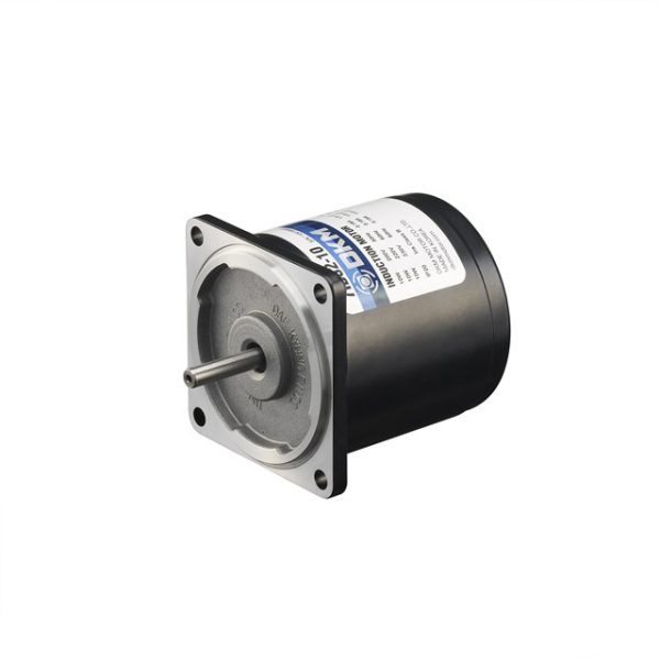
Motor DKM Hàn Quốc
Liên hệ -
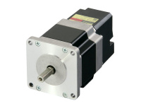
Motor Oriental tại Hà Nội
Liên hệ -
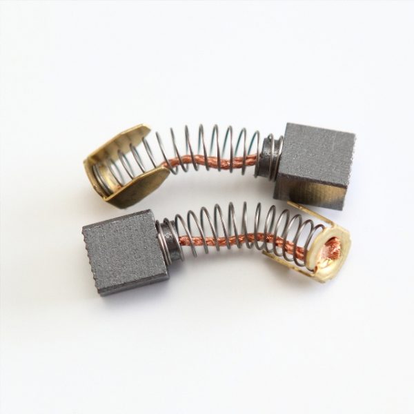
chổi than
Liên hệ -
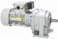
Động cơ TPG tại Hà Nam
Liên hệ

/5
Dựa trên đánh giá
Đánh giá
Chưa có đánh giá nào.