
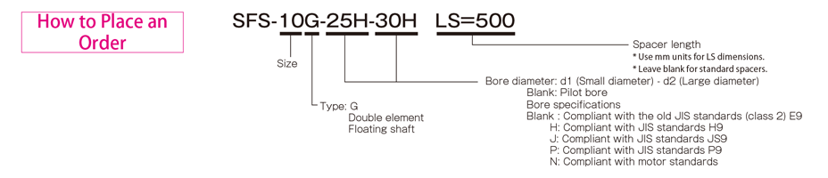
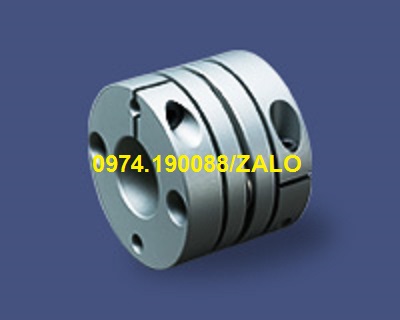
SFS Models
Liên hệ
Chúng tôi là nhà phân phối chính thức và duy nhất các sản phẩm của Miki Pulley tại thị trường Việt Nam, Quý khách có nhu cầu về các sản phẩm của Miki Pulley vui lòng liên hệ trực tiếp với chúng tôi để được tư vấn nhanh hơn.
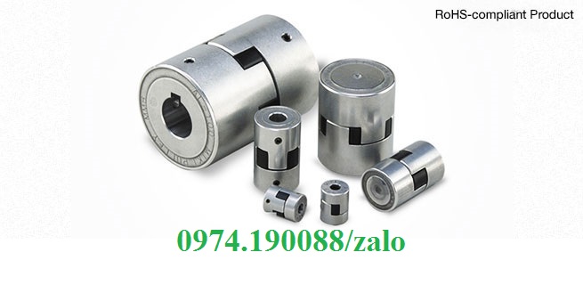
Hotline: 0974190088/Zalo
Email: vuonguoc@gmail.com
SFS Models
SFS Models Specifications
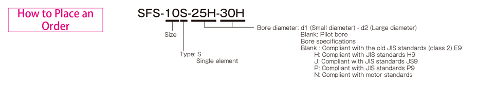
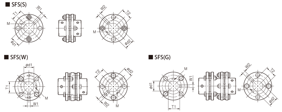
SFS (S) Types
[Specifications]
| Model | Rated torque[N・m] | Misalignment | Max. rotation speed[min-1] | Torsional stiffness[N・m/rad] | Axial stiffness[N/mm] | Moment of inertia[kg・m2] | Mass[kg] | |
|---|---|---|---|---|---|---|---|---|
| Angular[°] | Axial[mm] | |||||||
| SFS-05S | 20 | 1 | ±0.6 | 25000 | 16000 | 43 | 0.11×10⁻³ | 0.30 |
| SFS-06S | 40 | 1 | ±0.8 | 20000 | 29000 | 45 | 0.30×10⁻³ | 0.50 |
| SFS-08S | 80 | 1 | ±1.0 | 17000 | 83000 | 60 | 0.87×10⁻³ | 1.00 |
| SFS-09S | 180 | 1 | ±1.2 | 15000 | 170000 | 122 | 1.60×10⁻³ | 1.40 |
| SFS-10S | 250 | 1 | ±1.4 | 13000 | 250000 | 160 | 2.60×10⁻³ | 2.10 |
| SFS-12S | 450 | 1 | ±1.6 | 11000 | 430000 | 197 | 6.50×10⁻³ | 3.40 |
| SFS-14S | 800 | 1 | ±1.8 | 9500 | 780000 | 313 | 9.90×10⁻³ | 4.90 |
*Max. rotation speed does not take into account dynamic balance.
*The moment of inertia and mass are measured for the maximum bore diameter.
[Dimensions]

| Model | d1・d2 | D | N | L | LF | S | F | K | M | ||
|---|---|---|---|---|---|---|---|---|---|---|---|
| Pilot bore | Min. | Max. | |||||||||
| SFS-05S | 7 | 8 | 20 | 56 | 32 | 45 | 20 | 5 | 11 | 24 | 4-M5×22 |
| SFS-06S | 7 | 8 | 25 | 68 | 40 | 56 | 25 | 6 | 10 | 30 | 4-M6×25 |
| SFS-08S | 10 | 11 | 35 | 82 | 54 | 66 | 30 | 6 | 11 | 38 | 4-M6×29 |
| SFS-09S | 10 | 11 | 38 | 94 | 58 | 68 | 30 | 8 | 21 | 42 | 4-M8×36 |
| SFS-10S | 15 | 16 | 42 | 104 | 68 | 80 | 35 | 10 | 16 | 48 | 4-M8×36 |
| SFS-12S | 18 | 19 | 50 | 126 | 78 | 91 | 40 | 11 | 23 | 54 | 4-M10×45 |
| SFS-14S | 20 | 22 | 60 | 144 | 88 | 102 | 45 | 12 | 31 | 61 | 4-M12×54 |
*Pilot bores are to be drilled into the part.
*The nominal diameter of the reamer bolt M is equal to the quantity minus the nominal diameter of the screw threads times the nominal length.
[Standard bore diameter]
| Model | Standard bore diameter d1・d2 [mm] | |||||||||||||||||||||||||||
|---|---|---|---|---|---|---|---|---|---|---|---|---|---|---|---|---|---|---|---|---|---|---|---|---|---|---|---|---|
| 8 | 9 | 10 | 11 | 12 | 14 | 15 | 16 | 17 | 18 | 19 | 20 | 22 | 24 | 25 | 28 | 30 | 32 | 35 | 38 | 40 | 42 | 45 | 48 | 50 | 55 | 56 | 60 | |
| SFS-05S | ● | ● | ● | ● | ● | ● | ● | ● | ● | ● | ● | ● | ||||||||||||||||
| SFS-06S | ● | ● | ● | ● | ● | ● | ● | ● | ● | ● | ● | ● | ● | ● | ● | |||||||||||||
| SFS-08S | ● | ● | ● | ● | ● | ● | ● | ● | ● | ● | ● | ● | ● | ● | ● | ● | ||||||||||||
| SFS-09S | ● | ● | ● | ● | ● | ● | ● | ● | ● | ● | ● | ● | ● | ● | ● | ● | ● | |||||||||||
| SFS-10S | ● | ● | ● | ● | ● | ● | ● | ● | ● | ● | ● | ● | ● | ● | ● | |||||||||||||
| SFS-12S | ● | ● | ● | ● | ● | ● | ● | ● | ● | ● | ● | ● | ● | ● | ● | |||||||||||||
| SFS-14S | ● | ● | ● | ● | ● | ● | ● | ● | ● | ● | ● | ● | ● | ● | ● | ● | ||||||||||||
* Bore diameters marked with ● are supported as standard bore diameter. See the standard hole-drilling standards for information.
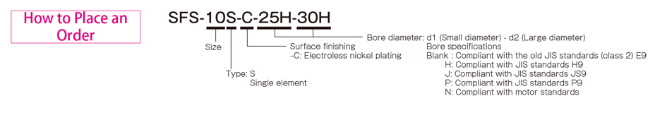
SFS (S-C) Types
[Specifications]
| Model | Rated torque[N・m] | Misalignment | Max. rotation speed[min-1] | Torsional stiffness[N・m/rad] | Axial stiffness[N/mm] | Moment of inertia[kg・m2] | Mass[kg] | |
|---|---|---|---|---|---|---|---|---|
| Angular[°] | Axial[mm] | |||||||
| SFS-05S-C | 15 | 1 | ±0.6 | 25000 | 16000 | 43 | 0.11×10⁻³ | 0.30 |
| SFS-06S-C | 30 | 1 | ±0.8 | 20000 | 29000 | 45 | 0.30×10⁻³ | 0.50 |
| SFS-08S-C | 60 | 1 | ±1.0 | 17000 | 83000 | 60 | 0.87×10⁻³ | 1.00 |
| SFS-09S-C | 135 | 1 | ±1.2 | 15000 | 170000 | 122 | 1.60×10⁻³ | 1.40 |
| SFS-10S-C | 190 | 1 | ±1.4 | 13000 | 250000 | 160 | 2.60×10⁻³ | 2.10 |
| SFS-12S-C | 340 | 1 | ±1.6 | 11000 | 430000 | 197 | 6.50×10⁻³ | 3.40 |
| SFS-14S-C | 600 | 1 | ±1.8 | 9500 | 780000 | 313 | 9.90×10⁻³ | 4.90 |
*Max. rotation speed does not take into account dynamic balance.
*The moment of inertia and mass are measured for the maximum bore diameter.
[Dimensions]
| Model | d1・d2 | D | N | L | LF | S | F | K | M | |
|---|---|---|---|---|---|---|---|---|---|---|
| Min. | Max. | |||||||||
| SFS-05S-C | 8 | 20 | 56 | 32 | 45 | 20 | 5 | 11 | 24 | 4-M5×22 |
| SFS-06S-C | 8 | 25 | 68 | 40 | 56 | 25 | 6 | 10 | 30 | 4-M6×25 |
| SFS-08S-C | 11 | 35 | 82 | 54 | 66 | 30 | 6 | 11 | 38 | 4-M6×29 |
| SFS-09S-C | 11 | 38 | 94 | 58 | 68 | 30 | 8 | 21 | 42 | 4-M8×36 |
| SFS-10S-C | 16 | 42 | 104 | 68 | 80 | 35 | 10 | 16 | 48 | 4-M8×36 |
| SFS-12S-C | 19 | 50 | 126 | 78 | 91 | 40 | 11 | 23 | 54 | 4-M10×45 |
| SFS-14S-C | 22 | 60 | 144 | 88 | 102 | 45 | 12 | 31 | 61 | 4-M12×54 |
*The nominal diameter of the reamer bolt M is equal to the quantity minus the nominal diameter of the screw threads times the nominal length.
[Standard bore diameter]
| Model | Standard bore diameter d1・d2 [mm] | |||||||||||||||||||||||||||
|---|---|---|---|---|---|---|---|---|---|---|---|---|---|---|---|---|---|---|---|---|---|---|---|---|---|---|---|---|
| 8 | 9 | 10 | 11 | 12 | 14 | 15 | 16 | 17 | 18 | 19 | 20 | 22 | 24 | 25 | 28 | 30 | 32 | 35 | 38 | 40 | 42 | 45 | 48 | 50 | 55 | 56 | 60 | |
| SFS-05S-C | ● | ● | ● | ● | ● | ● | ● | ● | ● | ● | ● | ● | ||||||||||||||||
| SFS-06S-C | ● | ● | ● | ● | ● | ● | ● | ● | ● | ● | ● | ● | ● | ● | ● | |||||||||||||
| SFS-08S-C | ● | ● | ● | ● | ● | ● | ● | ● | ● | ● | ● | ● | ● | ● | ● | ● | ||||||||||||
| SFS-09S-C | ● | ● | ● | ● | ● | ● | ● | ● | ● | ● | ● | ● | ● | ● | ● | ● | ● | |||||||||||
| SFS-10S-C | ● | ● | ● | ● | ● | ● | ● | ● | ● | ● | ● | ● | ● | ● | ● | |||||||||||||
| SFS-12S-C | ● | ● | ● | ● | ● | ● | ● | ● | ● | ● | ● | ● | ● | ● | ● | |||||||||||||
| SFS-14S-C | ● | ● | ● | ● | ● | ● | ● | ● | ● | ● | ● | ● | ● | ● | ● | ● | ||||||||||||
* Bore diameters marked with ● are supported as standard bore diameter. See the standard hole-drilling standards for information.
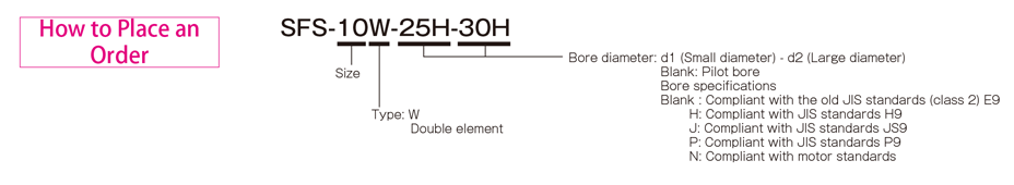
SFS (W) Types
[Specifications]
| Model | Rated torque[N・m] | Misalignment | Max. rotation speed[min-1] | Torsional stiffness[N・m/rad] | Axial stiffness[N/mm] | Moment of inertia[kg・m2] | Mass[kg] | ||
|---|---|---|---|---|---|---|---|---|---|
| Parallel[mm] | Angular[°] | Axial[mm] | |||||||
| SFS-05W | 20 | 0.2 | 1(On one side) | ±1.2 | 10000 | 8000 | 21 | 0.14×10⁻³ | 0.40 |
| SFS-06W | 40 | 0.3 | 1(On one side) | ±1.6 | 8000 | 14000 | 22 | 0.41×10⁻³ | 0.70 |
| SFS-08W | 80 | 0.3 | 1(On one side) | ±2.0 | 6800 | 41000 | 30 | 1.10×10⁻³ | 1.30 |
| SFS-09W | 180 | 0.5 | 1(On one side) | ±2.4 | 6000 | 85000 | 61 | 2.20×10⁻³ | 2.10 |
| SFS-10W | 250 | 0.5 | 1(On one side) | ±2.8 | 5200 | 125000 | 80 | 3.60×10⁻³ | 2.80 |
| SFS-12W | 450 | 0.7 | 1(On one side) | ±3.2 | 4400 | 215000 | 98 | 9.20×10⁻³ | 4.90 |
| SFS-14W | 800 | 0.7 | 1(On one side) | ±3.9 | 3800 | 390000 | 156 | 15.00×10⁻³ | 7.10 |
*Max. rotation speed does not take into account dynamic balance.
*The moment of inertia and mass are measured for the maximum bore diameter.
[Dimensions]

| Model | d1・d2 | D | N | L | LF | LP | S | F | d3 | K | M | ||
|---|---|---|---|---|---|---|---|---|---|---|---|---|---|
| Pilot bore | Min. | Max. | |||||||||||
| SFS-05W | 7 | 8 | 20 | 56 | 32 | 58 | 20 | 8 | 5 | 4 | 20 | 24 | 8-M5×15 |
| SFS-06W | 7 | 8 | 25 | 68 | 40 | 74 | 25 | 12 | 6 | 3 | 24 | 30 | 8-M6×18 |
| SFS-08W | 10 | 11 | 35 | 82 | 54 | 84 | 30 | 12 | 6 | 2 | 28 | 38 | 8-M6×20 |
| SFS-09W | 10 | 11 | 38 | 94 | 58 | 98 | 30 | 22 | 8 | 12 | 32 | 42 | 8-M8×27 |
| SFS-10W | 15 | 16 | 42 | 104 | 68 | 110 | 35 | 20 | 10 | 7 | 34 | 48 | 8-M8×27 |
| SFS-12W | 18 | 19 | 50 | 126 | 78 | 127 | 40 | 25 | 11 | 10 | 40 | 54 | 8-M10×32 |
| SFS-14W | 20 | 22 | 60 | 144 | 88 | 144 | 45 | 30 | 12 | 15 | 46 | 61 | 8-M12×38 |
*Pilot bores are to be drilled into the part.
*The nominal diameter of the reamer bolt M is equal to the quantity minus the nominal diameter of the screw threads times the nominal length.
[Standard bore diameter]
| Model | Standard bore diameter d1・d2 [mm] | |||||||||||||||||||||||||||
|---|---|---|---|---|---|---|---|---|---|---|---|---|---|---|---|---|---|---|---|---|---|---|---|---|---|---|---|---|
| 8 | 9 | 10 | 11 | 12 | 14 | 15 | 16 | 17 | 18 | 19 | 20 | 22 | 24 | 25 | 28 | 30 | 32 | 35 | 38 | 40 | 42 | 45 | 48 | 50 | 55 | 56 | 60 | |
| SFS-05W | ● | ● | ● | ● | ● | ● | ● | ● | ● | ● | ● | ● | ||||||||||||||||
| SFS-06W | ● | ● | ● | ● | ● | ● | ● | ● | ● | ● | ● | ● | ● | ● | ● | |||||||||||||
| SFS-08W | ● | ● | ● | ● | ● | ● | ● | ● | ● | ● | ● | ● | ● | ● | ● | ● | ||||||||||||
| SFS-09W | ● | ● | ● | ● | ● | ● | ● | ● | ● | ● | ● | ● | ● | ● | ● | ● | ● | |||||||||||
| SFS-10W | ● | ● | ● | ● | ● | ● | ● | ● | ● | ● | ● | ● | ● | ● | ● | |||||||||||||
| SFS-12W | ● | ● | ● | ● | ● | ● | ● | ● | ● | ● | ● | ● | ● | ● | ● | |||||||||||||
| SFS-14W | ● | ● | ● | ● | ● | ● | ● | ● | ● | ● | ● | ● | ● | ● | ● | ● | ||||||||||||
* Bore diameters marked with ● are supported as standard bore diameter. See the standard hole-drilling standards for information.
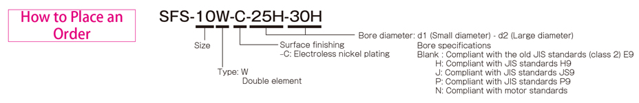
SFS (W-C) Types
[Specifications]
| Model | Rated torque[N・m] | Misalignment | Max. rotation speed[min-1] | Torsional stiffness[N・m/rad] | Axial stiffness[N/mm] | Moment of inertia[kg・m2] | Mass[kg] | ||
|---|---|---|---|---|---|---|---|---|---|
| Parallel[mm] | Angular[°] | Axial[mm] | |||||||
| SFS-05W-C | 15 | 0.2 | 1(On one side) | ±1.2 | 10000 | 8000 | 21 | 0.14×10⁻³ | 0.40 |
| SFS-06W-C | 30 | 0.3 | 1(On one side) | ±1.6 | 8000 | 14000 | 22 | 0.41×10⁻³ | 0.70 |
| SFS-08W-C | 60 | 0.3 | 1(On one side) | ±2.0 | 6800 | 41000 | 30 | 1.10×10⁻³ | 1.30 |
| SFS-09W-C | 135 | 0.5 | 1(On one side) | ±2.4 | 6000 | 85000 | 61 | 2.20×10⁻³ | 2.10 |
| SFS-10W-C | 190 | 0.5 | 1(On one side) | ±2.8 | 5200 | 125000 | 80 | 3.60×10⁻³ | 2.80 |
| SFS-12W-C | 340 | 0.6 | 1(On one side) | ±3.2 | 4400 | 215000 | 98 | 9.20×10⁻³ | 4.90 |
| SFS-14W-C | 600 | 0.7 | 1(On one side) | ±3.6 | 3800 | 390000 | 156 | 15.00×10⁻³ | 7.10 |
*Max. rotation speed does not take into account dynamic balance.
*The moment of inertia and mass are measured for the maximum bore diameter.
[Dimensions]
| Model | d1・d2 | D | N | L | LF | LP | S | F | d3 | K | M | |
|---|---|---|---|---|---|---|---|---|---|---|---|---|
| Min. | Max. | |||||||||||
| SFS-05W-C | 8 | 20 | 56 | 32 | 58 | 20 | 8 | 5 | 4 | 20 | 24 | 8-M5×15 |
| SFS-06W-C | 8 | 25 | 68 | 40 | 74 | 25 | 12 | 6 | 3 | 24 | 30 | 8-M6×18 |
| SFS-08W-C | 11 | 35 | 82 | 54 | 84 | 30 | 12 | 6 | 2 | 28 | 38 | 8-M6×20 |
| SFS-09W-C | 11 | 38 | 94 | 58 | 98 | 30 | 22 | 8 | 12 | 32 | 42 | 8-M8×27 |
| SFS-10W-C | 16 | 42 | 104 | 68 | 110 | 35 | 20 | 10 | 7 | 34 | 48 | 8-M8×27 |
| SFS-12W-C | 19 | 50 | 126 | 78 | 127 | 40 | 25 | 11 | 10 | 40 | 54 | 8-M10×32 |
| SFS-14W-C | 22 | 60 | 144 | 88 | 144 | 45 | 30 | 12 | 15 | 46 | 61 | 8-M12×38 |
*The nominal diameter of the reamer bolt M is equal to the quantity minus the nominal diameter of the screw threads times the nominal length.
[Standard bore diameter]
| Model | Standard bore diameter d1・d2 [mm] | |||||||||||||||||||||||||||
|---|---|---|---|---|---|---|---|---|---|---|---|---|---|---|---|---|---|---|---|---|---|---|---|---|---|---|---|---|
| 8 | 9 | 10 | 11 | 12 | 14 | 15 | 16 | 17 | 18 | 19 | 20 | 22 | 24 | 25 | 28 | 30 | 32 | 35 | 38 | 40 | 42 | 45 | 48 | 50 | 55 | 56 | 60 | |
| SFS-05W-C | ● | ● | ● | ● | ● | ● | ● | ● | ● | ● | ● | ● | ||||||||||||||||
| SFS-06W-C | ● | ● | ● | ● | ● | ● | ● | ● | ● | ● | ● | ● | ● | ● | ● | |||||||||||||
| SFS-08W-C | ● | ● | ● | ● | ● | ● | ● | ● | ● | ● | ● | ● | ● | ● | ● | ● | ||||||||||||
| SFS-09W-C | ● | ● | ● | ● | ● | ● | ● | ● | ● | ● | ● | ● | ● | ● | ● | ● | ● | |||||||||||
| SFS-10W-C | ● | ● | ● | ● | ● | ● | ● | ● | ● | ● | ● | ● | ● | ● | ● | |||||||||||||
| SFS-12W-C | ● | ● | ● | ● | ● | ● | ● | ● | ● | ● | ● | ● | ● | ● | ● | |||||||||||||
| SFS-14W-C | ● | ● | ● | ● | ● | ● | ● | ● | ● | ● | ● | ● | ● | ● | ● | ● | ||||||||||||
* Bore diameters marked with ● are supported as standard bore diameter. See the standard hole-drilling standards for information.
SFS (G) Types
[Specifications]
| Model | Rated torque[N・m] | Misalignment | Max. rotation speed[min-1] | Torsional stiffness[N・m/rad] | Axial stiffness[N/mm] | Moment of inertia[kg・m2] | Mass[kg] | ||
|---|---|---|---|---|---|---|---|---|---|
| Parallel[mm] | Angular[°] | Axial[mm] | |||||||
| SFS-05G | 20 | 0.5 | 1(On one side) | ±1.2 | 20000 | 8000 | 21 | 0.20×10⁻³ | 0.50 |
| SFS-06G | 40 | 0.5 | 1(On one side) | ±1.6 | 16000 | 14000 | 22 | 0.55×10⁻³ | 0.90 |
| SFS-08G | 80 | 0.5 | 1(On one side) | ±2.0 | 13000 | 41000 | 30 | 1.50×10⁻³ | 1.70 |
| SFS-09G | 180 | 0.6 | 1(On one side) | ±2.4 | 12000 | 85000 | 61 | 2.90×10⁻³ | 2.40 |
| SFS-10G | 250 | 0.6 | 1(On one side) | ±2.8 | 10000 | 125000 | 80 | 4.60×10⁻³ | 3.30 |
| SFS-12G | 450 | 0.8 | 1(On one side) | ±3.2 | 8000 | 215000 | 98 | 11.80×10⁻³ | 5.80 |
| SFS-14G | 800 | 0.9 | 1(On one side) | ±3.6 | 7000 | 390000 | 156 | 21.20×10⁻³ | 8.60 |
*Max. rotation speed does not take into account dynamic balance.
*The moment of inertia and mass are measured for the maximum bore diameter.
[Dimensions]

| Model | d1・d2 | D | N | L | LF | LS | S | F | K | M | ||
|---|---|---|---|---|---|---|---|---|---|---|---|---|
| Pilot bore | Min. | Max. | ||||||||||
| SFS-05G | 7 | 8 | 20 | 56 | 32 | 74 | 20 | 24 | 5 | 11 | 24 | 8-M5×22 |
| SFS-06G | 7 | 8 | 25 | 68 | 40 | 86 | 25 | 24 | 6 | 10 | 30 | 8-M6×25 |
| SFS-08G | 10 | 11 | 35 | 82 | 54 | 98 | 30 | 26 | 6 | 11 | 38 | 8-M6×29 |
| SFS-09G | 10 | 11 | 38 | 94 | 58 | 106 | 30 | 30 | 8 | 21 | 42 | 8-M8×36 |
| SFS-10G | 15 | 16 | 42 | 104 | 68 | 120 | 35 | 30 | 10 | 16 | 48 | 8-M8×36 |
| SFS-12G | 18 | 19 | 50 | 126 | 78 | 140 | 40 | 38 | 11 | 23 | 54 | 8-M10×45 |
| SFS-14G | 20 | 22 | 60 | 144 | 88 | 160 | 45 | 46 | 12 | 31 | 61 | 8-M12×54 |
*Pilot bores are to be drilled into the part.
*If you require a product with an LS dimension other than that above, contact Miki Pulley with your required dimension. Please contact Miki Pulley for assistance if LS ≧ 1000.
*The nominal diameter of the reamer bolt M is equal to the quantity minus the nominal diameter of the screw threads times the nominal length.
[Standard bore diameter]
| Model | Standard bore diameter d1・d2 [mm] | |||||||||||||||||||||||||||
|---|---|---|---|---|---|---|---|---|---|---|---|---|---|---|---|---|---|---|---|---|---|---|---|---|---|---|---|---|
| 8 | 9 | 10 | 11 | 12 | 14 | 15 | 16 | 17 | 18 | 19 | 20 | 22 | 24 | 25 | 28 | 30 | 32 | 35 | 38 | 40 | 42 | 45 | 48 | 50 | 55 | 56 | 60 | |
| SFS-05G | ● | ● | ● | ● | ● | ● | ● | ● | ● | ● | ● | ● | ||||||||||||||||
| SFS-06G | ● | ● | ● | ● | ● | ● | ● | ● | ● | ● | ● | ● | ● | ● | ● | |||||||||||||
| SFS-08G | ● | ● | ● | ● | ● | ● | ● | ● | ● | ● | ● | ● | ● | ● | ● | ● | ||||||||||||
| SFS-09G | ● | ● | ● | ● | ● | ● | ● | ● | ● | ● | ● | ● | ● | ● | ● | ● | ● | |||||||||||
| SFS-10G | ● | ● | ● | ● | ● | ● | ● | ● | ● | ● | ● | ● | ● | ● | ● | |||||||||||||
| SFS-12G | ● | ● | ● | ● | ● | ● | ● | ● | ● | ● | ● | ● | ● | ● | ● | |||||||||||||
| SFS-14G | ● | ● | ● | ● | ● | ● | ● | ● | ● | ● | ● | ● | ● | ● | ● | ● | ||||||||||||
* Bore diameters marked with ● are supported as standard bore diameter. See the standard hole-drilling standards for information.
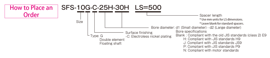
SFS (G-C) Types
[Specifications]
| Model | Rated torque[N・m] | Misalignment | Max. rotation speed[min-1] | Torsional stiffness[N・m/rad] | Axial stiffness[N/mm] | Moment of inertia[kg・m2] | Mass[kg] | ||
|---|---|---|---|---|---|---|---|---|---|
| Parallel[mm] | Angular[°] | Axial[mm] | |||||||
| SFS-05G-C | 15 | 0.5 | 1(On one side) | ±1.2 | 20000 | 8000 | 21 | 0.20×10⁻³ | 0.50 |
| SFS-06G-C | 30 | 0.5 | 1(On one side) | ±1.6 | 16000 | 14000 | 22 | 0.55×10⁻³ | 0.90 |
| SFS-08G-C | 60 | 0.5 | 1(On one side) | ±2.0 | 13000 | 41000 | 30 | 1.50×10⁻³ | 1.70 |
| SFS-09G-C | 135 | 0.6 | 1(On one side) | ±2.4 | 12000 | 85000 | 61 | 2.90×10⁻³ | 2.40 |
| SFS-10G-C | 190 | 0.6 | 1(On one side) | ±2.8 | 10000 | 125000 | 80 | 4.60×10⁻³ | 3.30 |
| SFS-12G-C | 340 | 0.8 | 1(On one side) | ±3.2 | 8000 | 215000 | 98 | 11.80×10⁻³ | 5.80 |
| SFS-14G-C | 600 | 0.9 | 1(On one side) | ±3.6 | 7000 | 390000 | 156 | 21.20×10⁻³ | 8.60 |
*Max. rotation speed does not take into account dynamic balance.
*The moment of inertia and mass are measured for the maximum bore diameter.
[Dimensions]
| Model | d1・d2 | D | N | L | LF | LS | S | F | K | M | ||
|---|---|---|---|---|---|---|---|---|---|---|---|---|
| Pilot bore | Min. | Max. | ||||||||||
| SFS-05G-C | 7 | 8 | 20 | 56 | 32 | 74 | 20 | 24 | 5 | 11 | 24 | 8-M5×22 |
| SFS-06G-C | 7 | 8 | 25 | 68 | 40 | 86 | 25 | 24 | 6 | 10 | 30 | 8-M6×25 |
| SFS-08G-C | 10 | 11 | 35 | 82 | 54 | 98 | 30 | 26 | 6 | 11 | 38 | 8-M6×29 |
| SFS-09G-C | 10 | 11 | 38 | 94 | 58 | 106 | 30 | 30 | 8 | 21 | 42 | 8-M8×36 |
| SFS-10G-C | 15 | 16 | 42 | 104 | 68 | 120 | 35 | 30 | 10 | 16 | 48 | 8-M8×36 |
| SFS-12G-C | 18 | 19 | 50 | 126 | 78 | 140 | 40 | 38 | 11 | 23 | 54 | 8-M10×45 |
| SFS-14G-C | 20 | 22 | 60 | 144 | 88 | 160 | 45 | 46 | 12 | 31 | 61 | 8-M12×54 |
* If you require a product with an LS dimension other than that above, contact Miki Pulley with your required dimension. Please contact Miki Pulley for assistance if LS ≧ 1000.
* Please note that when the LS dimension exceeds 100 mm with the electroless nickel plating specification (SFS- □ G-C), the insertion length of the shaft cannot exceed the LS dimension.
* The nominal diameter of the reamer bolt M is equal to the quantity minus the nominal diameter of the screw threads times the nominal length.
[Standard bore diameter]
| Model | Standard bore diameter d1・d2 [mm] | |||||||||||||||||||||||||||
|---|---|---|---|---|---|---|---|---|---|---|---|---|---|---|---|---|---|---|---|---|---|---|---|---|---|---|---|---|
| 8 | 9 | 10 | 11 | 12 | 14 | 15 | 16 | 17 | 18 | 19 | 20 | 22 | 24 | 25 | 28 | 30 | 32 | 35 | 38 | 40 | 42 | 45 | 48 | 50 | 55 | 56 | 60 | |
| SFS-05G-C | ● | ● | ● | ● | ● | ● | ● | ● | ● | ● | ● | ● | ||||||||||||||||
| SFS-06G-C | ● | ● | ● | ● | ● | ● | ● | ● | ● | ● | ● | ● | ● | ● | ● | |||||||||||||
| SFS-08G-C | ● | ● | ● | ● | ● | ● | ● | ● | ● | ● | ● | ● | ● | ● | ● | ● | ||||||||||||
| SFS-09G-C | ● | ● | ● | ● | ● | ● | ● | ● | ● | ● | ● | ● | ● | ● | ● | ● | ● | |||||||||||
| SFS-10G-C | ● | ● | ● | ● | ● | ● | ● | ● | ● | ● | ● | ● | ● | ● | ● | |||||||||||||
| SFS-12G-C | ● | ● | ● | ● | ● | ● | ● | ● | ● | ● | ● | ● | ● | ● | ● | |||||||||||||
| SFS-14G-C | ● | ● | ● | ● | ● | ● | ● | ● | ● | ● | ● | ● | ● | ● | ● | ● | ||||||||||||
* Bore diameters marked with ● are supported as standard bore diameter. See the standard hole-drilling standards for information
【Standard Hole-Drilling Standards】
SFS Models, SFS Models, SFS Models, SFS Models, SFS Models, SFS Models, SFS Models
SFS Models,
Sản phẩm tương tự
-
SPRFLEX
Liên hệ -
SFM Models
Liên hệ -
Rigid Couplings
Liên hệ -
Miki Pulley
Liên hệ


/5
Dựa trên đánh giá
Đánh giá
Chưa có đánh giá nào.